


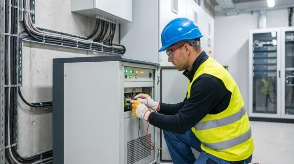


When commercial facilities scale their operations, legacy electrical systems are easily pushed beyond their limits. Ignoring the signs of an overloaded electrical service can lead to equipment damage, unexpected data loss, and severe safety hazards, such as arc flashes or electrical fires, that can halt business for weeks.
Catching capacity warning signs early prevents costly emergency repairs and catastrophic outages. This guide outlines the technical indicators of electrical system overload, helping facility managers proactively plan service upgrades before a major failure occurs.
Understanding Commercial Electrical Service Capacity and Amperage Limits
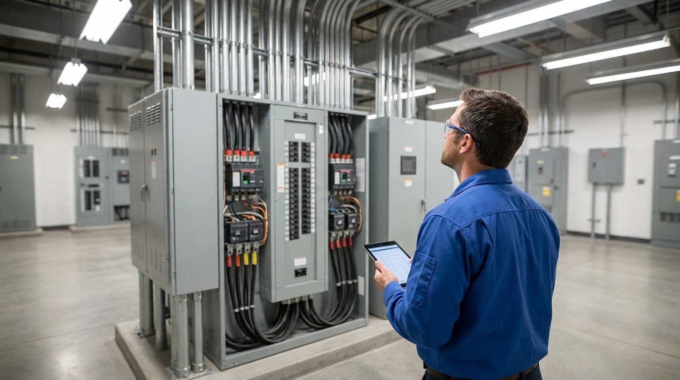
Commercial electrical capacity is the maximum amount of electrical current, measured in amperes, that a building’s infrastructure can safely distribute from the utility grid to internal equipment. Three core components define this maximum safety limit:
- The utility transformer capacity
- The physical gauge and thermal rating of the service entrance cables
- The maximum amperage rating of the main distribution panelboard
Every commercial structure has a strict ceiling on the amount of electric power it can safely draw from the grid without overheating.
The Hidden Electrical Demand of Modern Facility Growth
Gradual operational expansion often erodes the safety margins of a building’s power system without immediate detection. Retrofitting high-output LED lighting controls or integrating automated conveyor systems in warehouses can push older frameworks past their original design limits. These technology upgrades provide efficiency but increase the cumulative load on the distribution hardware.
In specialized commercial spaces, such as cold storage warehouses, medical clinics, and server rooms, the integration of specialized equipment and continuous HVAC climate control requires high-amperage electrical loads. These retrofits can exceed original system design specifications by 30% or more. This silent load growth often risks pushing the electrical infrastructure past safe operating limits during hot summer peak hours.
The Impact of High-Draw Technology and EV Charging
Integrating electric vehicle charging stations dramatically increases power demand in modern parking structures. Level 2 chargers draw between 30 and 80 amperes per circuit, while direct-current fast-charging stations can require up to 350 kilowatts of continuous power. Facility managers must calculate available capacity before integrating high-draw chargers into a legacy electrical grid.
A single DC fast-charging station often necessitates a dedicated utility transformer upgrade to maintain operational stability. Failing to audit the building’s electrical capacity before installing chargers can lead to localized voltage drops, transformer overloading, and premature equipment damage.
The Influence of Commercial Solar and Battery Storage
Integrating commercial solar arrays and on-site battery storage systems transforms how a facility interacts with the utility grid. While solar panels offset grid consumption during daylight hours, the associated inverters and bidirectional power flow require specialized switchgear. An outdated main panel often lacks the necessary busbar ratings to handle bidirectional power. Under NEC 705.12 (the 120% rule), the sum of the overcurrent devices supplying a busbar cannot exceed 120% of the busbar’s rating, making panel upgrades mandatory for many solar retrofits.
Service Amperage Explained: Commercial Benchmarks and Safety Envelopes
Commercial power capacities range from standard three-phase 200- and 400-amp panels to industrial-grade services of 4,000 amps. These capacities are bound by the size of the internal conductors and the capacity of the local utility supply transformer. Scaling a service often requires coordination with the utility provider to ensure that the external grid can support the increased internal demand.
Under the National Electrical Code (NEC) Articles 215.2(A)(1) and 230.42(A)(1), service and feeder conductors must be sized to handle 100% of non-continuous loads plus 125% of continuous loads (those running for three hours or more). This requirement effectively limits the continuous load on a standard overcurrent device to 80% of its rated capacity. Operating consistently at the edge of this safety threshold generates excessive heat, causing premature component degradation.
Older commercial properties built before the 1980s frequently rely on legacy 200-amp or 400-amp services that are entirely inadequate for modern, multi-zone HVAC systems and heavy office or manufacturing loads. Upgrading to a 600-amp, 800-amp, or larger three-phase service is a standard requirement during modern commercial tenant improvements.
Warning Sign: Commercial Breaker Tripping Issues and Main Breaker Stress
Circuit breakers act as mechanical safety devices that prevent overcurrent damage by interrupting the flow of electricity. When a breaker trips, it’s a diagnostic warning that the electrical load has reached a dangerous tipping point. Understanding the root cause of commercial breaker tripping issues is fundamental to maintaining a safe work environment.
The Critical Distinction Between Branch and Main Breaker Trips
A branch breaker trip indicates a localized issue, such as an overloaded circuit or a single malfunctioning appliance, containing the outage to a small zone. In contrast, a main breaker trip is a systemic capacity event that cuts power to an entire panelboard or the entire facility. This occurs because the cumulative demand of all active branch circuits has breached the main breaker’s safety threshold, signaling a facility-wide capacity deficit rather than a localized equipment fault.
Why Repeatedly Resetting Tripped Breakers Escalates Fire Risks
Continually resetting a tripped breaker without diagnosing the overload places severe mechanical and thermal stress on the contacts. Over time, this repetitive fatigue can weld the contacts together or degrade the thermal-magnetic trip elements, causing the breaker to fail in the closed position. When a breaker fails to trip during a subsequent overload, the supply conductors rapidly overheat, melting their insulation and causing localized arcing that can ignite surrounding structural materials.
Warning Sign: Building Voltage Sags and Flickering Lights
Voltage sags and fluctuations serve as major indicators that a facility is struggling with its power supply. These events demonstrate that the building’s infrastructure is incapable of maintaining stable electrical pressure under current operational loads. Consistent voltage sags in the building often precede more significant system failures.
Identifying Voltage Sags During Heavy Startups
Industrial equipment like air compressors, chillers, and large HVAC motors requires a massive inrush (starting) current that can be up to 6 times their running current. If the service transformer or feeder conductors are undersized, this sudden draw causes a severe voltage sag across the entire system. This sag causes light fixtures to flicker and can drop voltage below the operational thresholds of electronic equipment, leading to system resets and data corruption.
The Costly Impact of Dirty Power on Sensitive Commercial IT
Overloaded electrical systems often exhibit high levels of total harmonic distortion and voltage fluctuation, which degrade modern electronic power supplies. Sensitive assets, including server arrays, point-of-sale systems, and Computer Numerical Control machinery, rely on clean, stable sinusoidal AC waveforms. Operating these devices on overloaded, dirty power lines causes internal thermal stress, random microprocessor lockups, and premature motherboard failures.
Overheating Panels: Using Thermal Imaging to Detect Electrical Overloads
Heat is the natural byproduct of electrical resistance in any conducting material. A system operating at or near its maximum capacity limits will generate dangerous levels of thermal energy within its enclosures. Unchecked thermal energy rapidly degrades wire insulation and sparks devastating electrical fires.
The Role of Thermal Imaging in Electrical Panel Inspections
Certified electrical contractors use advanced infrared scanning to assess the safety of distribution systems while they are still active. Utilizing thermal imaging on electrical panels allows technicians to see invisible heat patterns without interrupting facility operations. This non-invasive diagnostic tool identifies potential failure points that the naked eye cannot detect.
Under NFPA 70B Standard for Electrical Equipment Maintenance, temperature differentials (Delta-T) are used to categorize electrical risk. A temperature difference of 4°C to 15°C between similar components under similar load indicates a moderate deficiency, while a Delta-T exceeding 15°C represents a critical fault requiring immediate intervention. Thermographic scans identify these hot spots on busbars, main lugs, and breaker contacts before they result in catastrophic failure.
How Florida’s Humidity and Ambient Heat Accelerate Panel Failure
Florida’s high ambient summer temperatures and humidity directly affect the performance of electrical infrastructure. According to NEC Table 310.15(B)(1) (or 310.16 depending on the code year), conductor ampacities must be derated when operating in ambient temperatures above 30°C (86°F). In hot mechanical rooms or outdoor enclosures where temperatures regularly exceed 40°C (104°F), an already overloaded system experiences accelerated thermal degradation, making routine infrared thermography under peak load conditions critical.
Electrical contractors must perform predictive maintenance scans while the facility operates under normal peak loads to gather effective data. Scanning during peak operations ensures that the thermal profile accurately reflects the system’s behavior under its most stressed conditions. Captured data helps facility managers understand which specific components are at the highest risk of heat-related failure.
Distinguishing Between Loose Terminal Connections and Direct Panel Overloads
Interpreting thermal scan data requires a nuanced understanding of how heat dissipates within electrical hardware. A localized heat signature typically points to a single loose or corroded wire termination. These issues can often be resolved by tightening connections or replacing a specific terminal.
Thermographic analysis easily distinguishes between localized component faults and systemic capacity limitations. A high-temperature signature isolated to a single terminal indicates high resistance, usually caused by a loose connection or corrosion. It can be remedied by cleaning and torquing the lug to the manufacturer’s specifications. Conversely, a uniform thermal stress profile across all three phases of a main panelboard, including the incoming main feeder cables and the busbars, indicates a systemic capacity overload that can only be resolved by upgrading the facility’s service capacity.
Strategic Growth Barriers: When Electrical Limits Prevent Facility Expansion
Electrical capacity often becomes a hard ceiling for business growth before physical square footage does. Facility managers may realize they cannot add a new production line, install rapid-recovery HVAC units, or execute tenant improvements because the existing service has zero remaining headroom. Proactively upgrading electrical services before ordering new machinery prevents costly delivery delays and operational downtime, transforming your power infrastructure from a bottleneck into a competitive advantage.
Auditory and Physical Warning Signs: Buzzing, Humming, and Discoloration
Under high current loads, loose physical connections and magnetic fields can cause audible vibrations. A low 60 Hz hum coming from panels or dry-type transformers is often caused by laminations or loose busbar mounting hardware vibrating under high magnetic stress. However, high-pitched buzzing, crackling, or hissing indicates active electrical arcing, which is an immediate fire hazard. Any physical warning signs, such as scorched enclosures, discolored breaker casings, warped cabinet doors, or a distinct, fishy smell of burning insulation, demand immediate emergency service.
Florida’s high humidity and heat accelerate material degradation, making these physical signs more common. Any discoloration around wiring or terminals suggests that the system has already experienced a thermal event. Addressing these sensory clues immediately is the only way to prevent a catastrophic fire.
Certain legacy electrical panels pose severe safety risks regardless of the load. Federal Pacific Electric Stab-Lok breakers are notorious for failing to trip during overcurrent events, with some tests showing failure rates over 50%. Similarly, Zinsco panels have design flaws that cause the aluminum busbars to corrode, causing the breaker contacts to overheat and fuse directly to the bus. If your facility has these legacy brands, immediate replacement is a critical safety priority.
How to Calculate and Verify Your Current Commercial Panel Capacity
Transitioning from observing symptoms to implementing solutions requires a move toward quantitative data. Precise measurements are key to understanding the true health of a commercial facility’s capacity. Professional diagnostics provide the clarity needed to make informed decisions about infrastructure investments.
Commercial Electrical Load Calculation Services
A qualified commercial electrical contractor performs a formal load calculation to determine the required service amperage. This methodology involves conducting a comprehensive inventory of all connected equipment, lighting, and HVAC systems. Professionals use demand factors specified in the National Electrical Code to distinguish among different types of electrical use.
Under Florida Statute Chapter 471, plans for any commercial electrical system exceeding 400 amperes at 240 volts (three-phase) or 800 amperes at 240 volts (single-phase), or with an estimated cost exceeding $50,000, must be designed and sealed by a licensed Florida Professional Engineer (PE). A formal NEC Article 220 load calculation accounts for continuous and non-continuous startups, and voltage drop to establish the precise service capacity required.
Implementing 30-Day Power Quality Logging and Demand Analysis
Under NEC 220.87, when adding load to an existing service, you must either perform a standard load calculation or use a 30-day power demand log to prove the existing service has sufficient headroom. Installing a calibrated power quality analyzer on the main service conductors captures real-time data on voltage, amperage, power factor, and transient spikes over a complete business cycle. This quantitative logging ensures you do not waste capital on unnecessary service upgrades or, conversely, overload a critical system.
The Financial and Operational Risks of Ignoring Capacity Warnings
Ignoring capacity warnings is a high-stakes gamble that eventually results in massive capital losses and severe safety hazards. The costs associated with a sudden system failure far outweigh the investment in a planned upgrade. Maintaining a reliable electrical system is a fundamental requirement for business continuity.
Catastrophic Power Failure and Unplanned Facility Downtime
An unexpected main breaker failure or panelboard arc flash can shut down facility operations for days or even weeks while replacement gear is on lead time. For medium-sized industrial facilities, unplanned downtime easily costs thousands of dollars per hour in lost productivity and idle labor. Proactive, scheduled service upgrades prevent emergency change-out premiums, premium shipping fees, and secondary damage to downstream machinery.
Accelerated Equipment Wear and Premature Motor Burnout
When an overloaded electrical service causes chronic low-voltage conditions, three-phase induction motors are forced to draw higher amperage to maintain their rated torque. This increased current draw leads to excessive internal heat, which scales exponentially with the square of the current. Every 10°C rise in winding temperature halves the operating life of a motor’s insulation, leading to premature stator burnout and costly motor replacements.
Code Violations, Fire Marshal Red Flags, and Insurance Denials
Operating an overloaded commercial electrical system violates NEC and OSHA safety standards, risking municipal fines or a shut-down order from the Fire Marshal. In the Tampa Bay area, local building departments require a licensed electrical contractor to secure permits for any service modification. If an electrical fire occurs and forensic investigators find the system was modified without permits, your property insurance carrier has grounds to deny coverage.
Strategic Next Steps: Safely Upgrading Your Commercial Power System
Upgrading a facility’s power capacity is a strategic physical asset enhancement that unlocks future business potential. It provides the foundation for modern technology integrations and long-term peace of mind. Taking a proactive approach allows for a more efficient and cost-effective transition.
Service Upgrades vs. Subpanel Integrations vs. Transformer Upgrades
Depending on the extent of your facility’s power demands, resolving capacity limits may involve localized routing changes, panel replacements, or utility-level coordination. The following table outlines how these strategies differ:
| Solution Type | Primary Purpose | Ideal Use Case | Key Considerations |
| Full Service Upgrade | Increases the total incoming electrical volume from the grid. | The facility’s total current draw consistently exceeds the 80% NEC continuous load safety envelope. | Requires replacement of main service conductors, panelboards, and disconnects (coordinated with utility providers such as TECO or Duke Energy). |
| Subpanel Integration | Adds physical circuit slots and redistributes localized branch loads. | The main panelboard has sufficient capacity, but specific rooms or departments lack physical space for new circuits. | Does not increase the building’s total electrical capacity, making it only a local routing fix. |
| Transformer Upgrade | Steps up the voltage or secondary capacity from the local utility grid. | Integrating high-draw equipment, such as heavy industrial machinery or multiple DC fast-charging stations. | Must be coordinated directly with the utility company and may involve long infrastructure lead times. |
Designing for Future-Proof Scalability and Operational Redundancy
A future-proof electrical design should plan for a 20% to 30% expansion margin to accommodate the next 10 to 15 years of operational growth. Specifying oversized conduits (such as installing 4-inch runs where 3-inch conduits are currently required) and leaving spare busbar space in the main switchgear simplify future capacity increases. In Florida, integrating a permanent generator docking station (such as a double-throw manual transfer switch or a generator quick-connect cabinet) ensures compliance and business continuity during seasonal tropical storms and utility outages.
Upgrade Your Commercial Power Infrastructure with Suncoast Power
Proactive electrical system audits protect your physical assets, maintain regulatory compliance, and provide a clear roadmap for safely scaling your operations. Suncoast Power brings over 40 years of expert experience to every Florida project. We specialize in the design, installation, and maintenance of complex electrical systems for airports, casinos, warehouses, and manufacturing facilities.
We understand the unique challenges of Florida’s environment and the rigorous requirements of the National Electrical Code. Contact us today to schedule a thorough commercial electrical capacity assessment for your facility.