


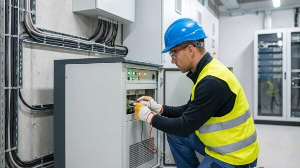


Managing high-amperage operations in environments like trade halls or casinos requires precise alignment of single-phase loads across L1, L2, and L3 lines on distribution sub-panels. Localized imbalances often create cascading failures that disrupt 24/7 business functions.
Severe imbalances lead to transformer overheating, excessive current on neutral conductors, and frequent circuit interruptions. Understanding the systematic auditing and redistribution of these electrical loads is the first step toward enhancing reliability and lowering energy consumption. Keep reading to learn more about technical methodologies for panel optimization, underfloor distribution, and long-term monitoring practices designed for high-density environments.
Why Is Phase Load Balancing Critical for Large-Scale Commercial Environments?
In large-scale commercial power distribution, phase load balancing is the strategic alignment of single-phase loads across L1, L2, and L3 lines to achieve uniform current draw. Proper phase balance optimizes panelboard capacity, prevents neutral conductor overheating, and reduces the voltage drop that can degrade the performance of sensitive electronic equipment.
The Mechanics of Three-Phase Power in Continuous Environments
Most commercial footprints rely on 120/208V or 277/480V four-wire, wye-connected three-phase configurations to distribute power. To maintain voltage stability and magnetic equilibrium within the upstream transformer, the current drawn by single-phase branch circuits must be split evenly among the L1, L2, and L3 line conductors.
Open-floor plans often aggregate thousands of single-phase loads like slot machines, digital signage, and point-of-sale terminals. These devices act as non-linear loads, meaning their impedance changes with the applied voltage and results in a non-sinusoidal current draw. When these loads connect between one line phase and the neutral conductor without proper coordination, an asymmetrical current flow develops across the system.
In four-wire systems, this imbalance prevents phase currents from canceling, leading to cumulative triplen harmonics in the neutral line. The third harmonic in 60 Hz North American systems occurs at 180 Hz, which compounds the distortion and causes the neutral conductor to carry up to 173% of the phase current. This condition subjects the neutral bus to thermal and mechanical stresses that can exceed UL 67 limits and National Electrical Code standards, leading to severe overheating, insulation breakdown, and localized fire hazards.
How Severe Phase Imbalance Triggers Premature Circuit Breaker Tripping
Low-voltage thermal-magnetic circuit breakers use bi-metallic trip mechanisms that react to the heating effect of RMS current. If one phase carries a disproportionate share of the total load, its pole reaches the thermal trip threshold before the panel capacity is reached. Unequal loading results in premature tripping even when the total facility power draw seems to be within the nominal ratings of the main disconnect.
In high-density commercial footprints, unexplained circuit interruptions frequently occur during peak-demand hours when individual phase current exceeds breaker setpoints. The National Electrical Code (NEC Article 210.20) mandates that overcurrent protection devices for continuous loads (running for three hours or more) be sized at no less than 125% of the continuous load plus 100% of the non-continuous load. When localized phase imbalances occur, individual phase currents can spike past these thermal-magnetic thresholds, causing localized nuisance trips long before the overall panel limit is reached.
Calculating Transformer Losses and Energy Waste From Voltage Unbalance
Current imbalance and voltage unbalance link directly to transformer inefficiency and resistive heat losses. In a 24/7 casino environment, a 3% voltage unbalance can result in a 10% increase in motor operating temperatures. This extra heat forces dry-type distribution transformers to operate at higher core temperatures, which accelerates the breakdown of winding insulation.
Excessive thermal stress causes significant core losses through elevated eddy currents and hysteresis, further contributing to transformer heating. NEMA MG-1 standards note that a small voltage unbalance can produce a current unbalance six to ten times greater in magnitude under load. This amplified current unbalance creates severe counter-rotating negative sequence magnetic fields, driving up winding temperatures and accelerating motor insulation degradation. These inefficiencies result in thousands of dollars in wasted kilowatt-hours and increased utility demand charges for the facility each year.
Common Causes of Phase Imbalance in Florida Casinos, Retail, and Event Venues
Phase imbalance in Florida’s commercial environments is rarely a static issue and often develops as a result of gradual facility changes. Expansions, machine reconfigurations, and temporary additions can shift the electrical equilibrium over several months or years. Facility managers must identify these exact trigger points to correct the power distribution permanently.
Concentration of Single-Phase Slot Machines and Retail Equipment
Gaming floors feature massive concentrations of single-phase electronic devices, including slot machines, bill validators, and player-tracking modules. These devices are typically grouped in physical banks or carousels and fed from local sub-panels. Technicians often load these sub-panels sequentially, grouping adjacent machines onto neighboring breaker positions. If the initial installation or subsequent machine floor refreshes fail to rotate phase connections, an entire carousel can end up drawing from L1 or L2 alone, leaving L3 heavily underutilized.
Large retail environments experience similar imbalances when point-of-sale systems, localized display lighting, and small refrigeration units are plugged into nearby convenience outlets. Installers frequently run branch circuits to the physically closest junction boxes or panel sections without reviewing the upstream phase alignment. This ad-hoc deployment creates a lopsided current draw, reducing the overall electrical headroom of the distribution sub-panel and triggering localized voltage sags during peak operations.
Floor Layout Reconfigurations and Unplanned Load Additions
Frequent floor plan alterations and tenant build-outs contribute significantly to systemic electrical imbalance because facility technicians or third-party vendors often plug high-draw equipment or temporary event taps into the nearest available circuit.
This process usually bypasses the master panel load schedule, creating uncoordinated modifications to the original design. In continuous casino environments or busy retail spaces, fast turnaround times for layout changes often lead to skipped load calculations. Over time, these additions pile hundreds of additional single-phase amperes onto specific sub-panel legs, making regular panel schedule updates the only way to track these changes and maintain long-term system health.
Phase Balancing for Commercial LED Retrofits
When commercial spaces undergo large-scale lighting retrofits to install energy-efficient LED fixtures, the load on dedicated lighting circuits typically drops by 50% to 70%. If these circuits were originally balanced against high-current HVAC fans or convenience receptacles on the same distribution sub-panels, this sudden reduction of resistive lighting loads creates an acute current imbalance across L1, L2, and L3. Electrical contractors must calculate the post-retrofit continuous current draw and re-sequence the remaining single-phase mechanical loads to maintain voltage stability.
Technical Methodology for Balancing Three-Phase Sub-Panels
Correcting phase imbalance requires a systematic approach rooted in precise data collection and physical electrical intervention. Licensed electricians use specialized diagnostic tools to quantify the extent of the imbalance before making any changes. This engineering-backed methodology ensures that adjustments result in a more efficient and reliable power distribution network.
Step 1: Perform Comprehensive Electrical Audits and Thermal Imaging
The baseline of a commercial electrical audit involves utilizing calibrated, true root mean square clamp meters and multi-channel power quality analyzers to log data during peak operational hours. Technicians measure phase-to-phase and phase-to-neutral voltages, individual line currents, power factors, and total harmonic distortion. This comprehensive energy efficiency audit establishes how dynamic single-phase loads perform under full operational stress.
Under load, technicians perform thermographic imaging of all panelboards and transformer terminations in accordance with NFPA 70B standards. Infrared cameras identify thermal anomalies, such as high-resistance terminal connections or overheating neutral lugs, revealing localized thermal stress and identifying failing contacts before they can cause a system-wide interruption.
Step 2: Analyze Phase Load Schedules and Current Measurements
Once the raw current data for L1, L2, and L3 is recorded, electricians calculate the percentage of current unbalance using the standard NEMA formula:
Current Unbalance (%) = (Max Deviation from Average Current / Average Current) × 100
For instance, if measured phase currents are 140A, 165A, and 130A, the average is 145A. The maximum deviation from this average is 20A (165A – 145A), resulting in a current unbalance of 13.8%. This calculation helps identify which specific branch circuits must be targeted for redistribution.
Logged field measurements are cross-referenced with archived panel schedules to identify the branch circuits powering continuous high-draw equipment. Technicians also analyze time-of-use patterns over 24-to-72-hour intervals, as critical phase imbalances often occur cyclically during specific shifts or event setups. Mapping these trends prevents a balancing solution that inadvertently creates a new imbalance during off-peak hours.
Step 3: Execute Strategic Physical Circuit Redistribution and Phase Swapping
Equalizing amperage loads requires shifting single-pole branch-circuit conductors to alternative phase lugs. Electricians must first de-energize the distribution sub-panel and execute strict OSHA Lockout/Tagout protocols. Based on the revised engineering load schedule, conductors are carefully migrated. All modified terminations are then torque-tested with a calibrated torque wrench to manufacturer specifications (typically in inch-pounds) to prevent loose, high-resistance connections.
Following physical circuit migration, electricians update the panel directory on-site and archive the digital load schedule. The system is re-energized, and technicians perform real-time verification of phase balance using RMS clamp meters under peak load conditions, backed by a follow-up thermographic scan to confirm the elimination of thermal anomalies.
Advanced Techniques for Large-Scale Commercial Footprints
Modern infrastructure design strategies offer advanced ways to facilitate ongoing phase alignment in massive architectural plans. These technologies provide the flexibility needed to manage shifting electrical demands without frequent manual intervention. Implementing these solutions can significantly simplify the management of power systems in open-floor layouts.
Implementing Underfloor Modular Busways and Track Distribution
Underfloor or overhead track busway systems provide highly flexible power distribution for open-floor casino and exhibition layouts. These networks feature continuous busway tracks where modular tap-off units can be plugged in and relocated on demand. Integrating these systems eliminates the labor-intensive practice of pulling new conduit and running individual home runs back to the main sub-panel during layout reconfigurations.
Technicians maintain phase equilibrium directly at the point of use by deploying color-coded, mechanically keyed tap-off plug connectors. These connectors are factory-wired to pull from alternating line combinations (such as L1-N, L2-N, and L3-N) for adjacent floor drops. Distributing the load at the point of drop ensures near-perfect balance across the upstream distribution panel, neutralizing potential imbalances at the branch level.
Utilizing Smart Power Distribution Units and Automated Phase Compensators
Smart power distribution units feature integrated networked metering that provides real-time monitoring of current, voltage, and power factor across individual phases. By using staggered, phase-balanced outlet configurations within equipment racks, these units prevent localized overloading. The gathered telemetry alerts facility engineers to creeping current imbalances before thermal limits are breached.
Active power quality filters and dynamic phase compensators actively monitor load current and inject counter-phase current vectors to neutralize triplen harmonics in real time. These active systems redirect reactive currents, stabilize voltage sags, and balance current across the main feed lines. Implementing dynamic harmonic filtering can reduce total building energy consumption by eliminating resistive I²R heat losses in the neutral conductor.
Mixed-Load Management: Single-Phase Equipment and Three-Phase HVAC
Facilities that operate both heavy three-phase inductive loads and massive single-phase electronic loads require holistic management. Heavy equipment like rooftop HVAC chillers and escalators are sensitive to the voltage imbalances caused by unequal single-phase distribution. These imbalances propagate upstream and degrade the efficiency of three-phase motors across the entire building.
Under NEMA MG-1 Section 14.36, a three-phase motor can operate at rated load only if voltage unbalance is maintained below 1%. If the voltage unbalance reaches 3%, the motor must be derated to 90% of its rated capacity; at 5% unbalance, the motor must be derated to 75% to prevent thermal breakdown of winding insulation. Additionally, installing K-factor transformers (such as K-13 or K-20) helps mitigate the harmonic heat generated by non-linear loads, utilizing double-sized neutral busbars to safely handle triplen harmonics without derating.
| Voltage Unbalance | NEMA Derating Factor | Approximate Winding Temperature Rise | Operational Recommendation |
| 1% or less | 1.00 | 0% (Base Winding Temp) | Standard continuous operation allowed. |
| 2% | 0.95 | +8% temperature rise | Acceptable; monitor for localized hot spots. |
| 3% | 0.90 | +18% temperature rise | Derate motor capacity; investigate phase balance immediately. |
| 4% | 0.82 | +32% temperature rise | Significant derating required; high risk of premature insulation failure. |
| 5% | 0.75 | +50% temperature rise | Critical threshold; operation not recommended without substantial load reduction. |
Long-Term Maintenance and Monitoring Strategies
Phase balancing is an ongoing operational discipline, rather than a one-time fix for large commercial facilities. Dynamic environments require constant attention to ensure that new equipment or layout changes don’t degrade system efficiency. Establishing a long-term monitoring strategy remains the most reliable way to maintain peak performance and system reliability.
Establishing Real-Time Power Quality Monitoring and Smart Metering
Permanent power quality monitoring systems provide continuous oversight of main switchgear and high-amperage distribution sub-panels. These systems can send automated alerts to the engineering team if the phase unbalance percentage exceeds a pre-set threshold. Proactive notification allows for corrections before a breaker trips or a transformer overheats.
Smart meters and historical trend analysis help facility directors link power quality metrics directly to utility billing data. According to the Department of Energy, maintaining voltage unbalance below 1% at motor terminals maximizes equipment lifespan. Annual thermographic inspections should remain a core part of the protocol to detect physical signs of stress.
Protocol for Future Floor Layout Changes and Equipment Additions
To prevent gradual drift into phase asymmetry, engineering teams should establish a structured protocol for all layout modifications and equipment additions:
- Mandatory Pre-Connection Reviews: Perform a localized load impact analysis before adding new machine banks, heavy refrigeration, or intensive LED lighting, ensuring the single-phase load is assigned to the phase leg with the highest current headroom.
- Standardized Worksheets: Equip field technicians with load distribution templates that log current draw on L1, L2, and L3 before and immediately after any electrical modification.
- Precise Labeling and Digitization: Enforce strict circuit-tagging protocols and update digital panel schedules in real time, eliminating outdated physical door charts.
- Harmonic Evaluations: Conduct a comprehensive harmonic current assessment whenever massive non-linear loads are added, utilizing active filtering if total harmonic distortion exceeds IEEE 519 limits.
Schedule An On-Site Assessment With Suncoast Power Today
Proper phase load balancing across high-amperage distribution networks eliminates parasitic transformer heat losses and prevents catastrophic, unplanned downtime. Aligning single-phase loads reduces harmonic distortion, stabilizes voltage levels, and extends the operational lifespan of sensitive solid-state equipment. Suncoast Power utilizes advanced diagnostic telemetry and thermal imaging to identify systemic phase imbalances and execute safe, engineered remediation strategies.
Suncoast Power has over 40 years of expertise as Tampa’s premier commercial electrical contractor. Our team is ready to evaluate your sub-panels and improve your energy performance. Contact us today to schedule your comprehensive power quality audit and ensure your Florida facility remains powered reliably.