





Commercial facilities in Florida face unique risks from frequent grid instability and severe weather events. The sudden loss of utility power in a 50,000-square-foot warehouse or a high-traffic airport like Tampa International creates safety hazards that complicate emergency evacuation procedures. These risks include obscured trip points and collision risks in high-occupancy zones where visibility vanishes instantly. For over 30 years, Suncoast Power has designed and installed the emergency lighting transfer switches required to bridge the gap between normal utility feeds and backup power.
Establishing code-compliant emergency backup infrastructure protects building occupants and ensures continuous business operations during grid failures. This analysis provides the technical protocols for designing, installing, and maintaining these systems in accordance with National Electrical Code Article 700, NFPA 101, and related municipal safety codes.
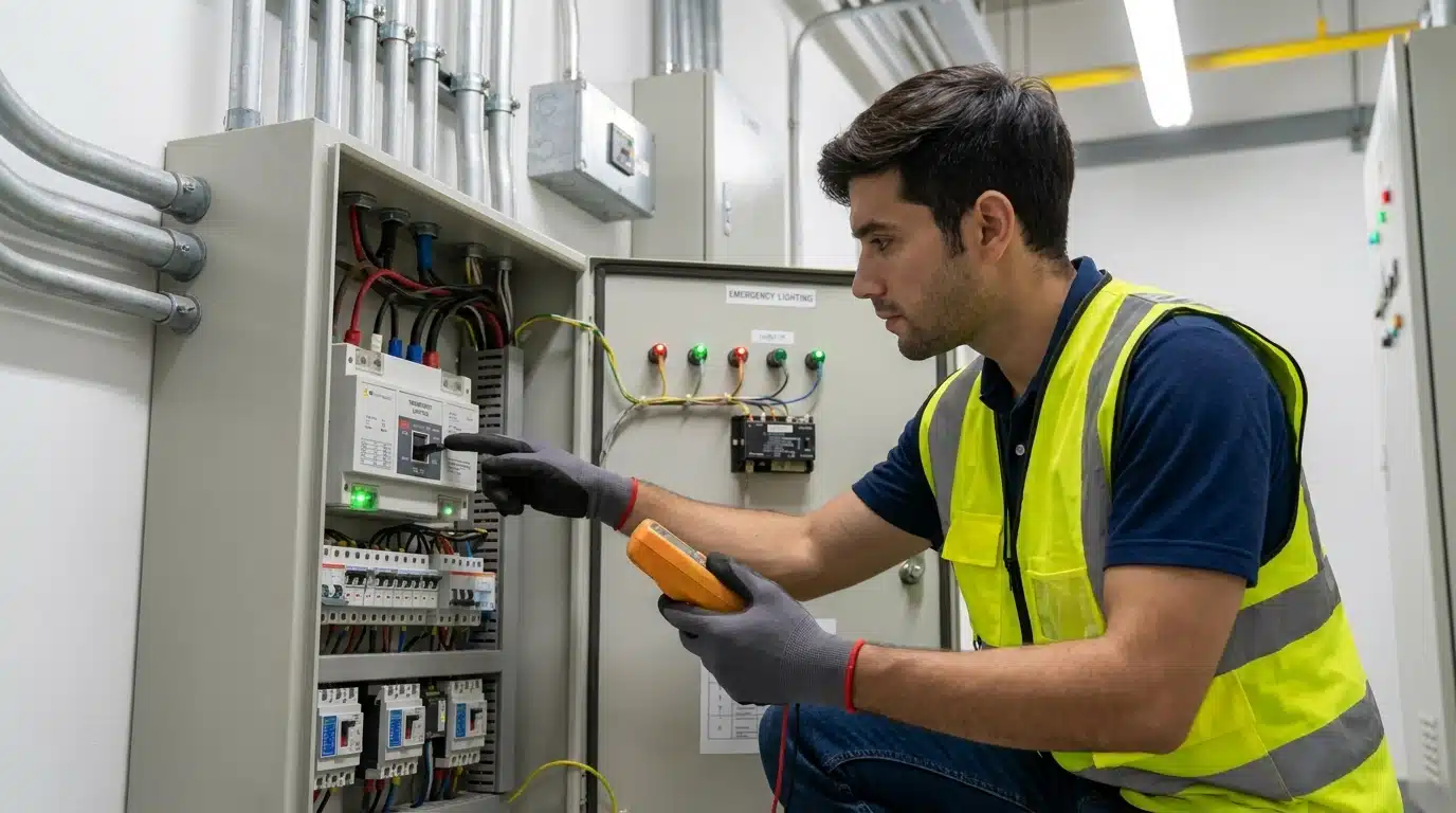
The Regulatory Framework: NEC Article 700, NFPA 101, and Underwriters Laboratories Standards
Commercial backup power must satisfy overlapping mandates from the National Fire Protection Association and the National Electrical Code. Compliance with these standards is verified by local Authorities Having Jurisdiction during commissioning and annual life-safety inspections.
National Fire Protection Association 101 Life Safety Code and Egress Illumination Requirements
The National Fire Protection Association 101 Life Safety Code mandates that emergency egress illumination remain active for at least 90 minutes following a primary power failure. This requirement applies to designated stairs, aisles, corridors, ramps, and escalators leading to an exit.
The code specifies that emergency lighting must provide an initial average of 1 foot-candle at floor level, which may decline to an average of 0.6 foot-candles over the 90-minute emergency period. Illumination must never drop below 0.1 foot-candle at any specific point along the egress path, and designers must maintain a maximum-to-minimum uniformity ratio of 40:1 to eliminate dangerous dark spots.
Emergency illumination requirements also cover exit discharge components, including exterior walkways leading to a public way. AHJs verify these levels with calibrated light meters during the final commissioning phase.
NEC Article 700 and Electrical Requirements for Emergency Systems
NEC Article 700 governs electrical systems that provide illumination, power, or both, to designated areas and equipment during a utility failure. These life-safety systems must be designed to supply, distribute, and control electricity within 10 seconds of a primary power interruption, as mandated by NEC 700.12.
NEC 700.10(B) strictly requires the physical separation of emergency system wiring from all other wiring. Emergency conductors cannot occupy the same raceways, cables, boxes, or cabinets as normal branch circuits, with narrow exceptions such as within transfer-switch enclosures or individual luminaires with dual feeds.
All emergency system equipment must be listed for emergency use under NEC 700.5. Additionally, under NEC 700.3(F), facilities with a single permanent generator must have a permanent means of switching to connect a portable or temporary alternate power source. This ensures that egress systems remain functional during routine generator maintenance or repair.
Deciphering UL 924 vs. UL 1008: The Crucial Differences
While both UL 924 and UL 1008 devices are integral to emergency lighting networks, they serve separate electrical functions and fall under different safety and listing standards. Selecting the wrong device violates code and risks system failure during an emergency.
| Feature or Specification | UL 924 Automatic Load Control Relay | UL 1008 Branch Circuit Emergency Lighting Transfer Switch |
| NEC Classification | NEC 700.26 | NEC 700.25 |
| Primary Function | Bypasses local controls (switches, dimmers, sensors) to force lights on at 100% output during a power loss. | Physically transfers a branch circuit’s electrical load from normal utility power to emergency backup power. |
| Power Source Connections | Single emergency branch circuit (acts as an inline control override). | Two independent power sources (Normal/Utility Feed and Emergency/Generator/Inverter Feed). |
| Conductor Switching | Switches only the ungrounded (hot) control conductor. | Switches both the ungrounded (hot) and grounded (neutral) conductors to maintain isolation. |
| Fault Current Rating | Standard branch-circuit rating (typically limited to the local breaker capacity). | High fault-withstand ratings (typically 10,000 Amps or higher) to survive high-energy transfer events. |
| Permitted Use as Transfer Equipment | No. NEC 700.26 explicitly prohibits the use of an ALCR as a source-to-source transfer switch. | Yes. Listed and approved for branch-level source-to-source transfer operations. |
Understanding UL 924 Emergency Lighting Control and Load Control Relays
A UL 924 Automatic Load Control Relay monitors normal utility power on a local branch circuit to override control devices (such as wall switches, occupancy sensors, or digital dimmers) during a utility outage. Because an ALCR does not transfer load between separate sources, it is wired in line with a single, continuously powered emergency branch circuit. Upon sensing a normal power interruption, the internal relay drops out, bypassing all local dimming or switching controls and routing emergency power directly to the luminaires at 100% brightness.
Modern UL 924-compliant devices require an active normal power sensing lead connected to the same branch circuit as the local control switch. This design ensures that a localized branch-circuit breaker trip will activate the emergency lights in that zone, even if the building’s main utility feed remains active. This localized failsafe prevents dark spots caused by sub-panel or individual circuit failures.
Selecting a UL 1008 Emergency Lighting Transfer Switch for Branch Circuits
A UL 1008 Branch Circuit Emergency Lighting Transfer Switch is a source-to-source transfer device that physically disconnects a branch circuit from normal utility power and connects it to a backup source (such as an emergency generator or centralized inverter). Unlike ALCRs, a BCELTS is listed to handle high short-circuit currents, typically rated for fault-withstand capacities up to 10,000 Amps. This ensures the mechanical integrity of the internal switching mechanism under extreme thermal and mechanical stress during fault conditions.
To prevent ground loops and backfeeding, dual-pole UL 1008 switches transition both the ungrounded (hot) and grounded (neutral) conductors. Switching the neutral is particularly critical when the emergency generator is configured as a Separately Derived System with its own grounded neutral-to-frame bond. Solid-neutral transfer switches should be used only when the normal and emergency systems share a single, unbroken neutral plane, preventing multiple ground paths that would otherwise desensitize ground-fault protection devices.
Comparing Applications: When to Specify UL 924 versus UL 1008
Engineers must select the device based on source-delivery architecture. Specify a UL 924 ALCR when the local branch circuit is fed from an emergency panelboard that is already downstream of a primary UL 1008 automatic transfer switch (such as a centralized battery inverter or a continuously energized emergency generator bus). In this configuration, the ALCR’s only role is to bypass local wall switches, occupancy sensors, or dimming circuits.
Conversely, specify a UL 1008 BCELTS when the individual branch circuit must switch between two distinct power sources at the local room level (for example, switching from a normal local lighting panel to an emergency generator feed). Under NEC 700.26, a UL 924 ALCR must never be used to transfer a load between two separate power sources.
Core Components of a Commercial Emergency Lighting System
A reliable commercial backup lighting wiring system consists of several integrated components that must work in perfect synchrony. These components provide a layered defense that starts at the main electrical room and extends to every individual light fixture. If any single part of this chain fails, the entire life-safety system may be compromised. When these pieces communicate seamlessly, egress paths stay illuminated.
Automatic Transfer Switches at the Panel Level
At the service entrance or distribution level, a panel-level Automatic Transfer Switch monitors utility voltage. When the utility voltage on any phase drops below a preset threshold (typically 80% of nominal), the ATS initiates a generator start command via dry contacts. Once the generator frequency and voltage stabilize within nominal tolerances, the ATS disconnects the normal utility bus and transfers the emergency panelboards to the generator feeder within the 10-second window mandated by NEC 700.12.
Shunt and Bypass Relays for Downstream Lighting Override
Downstream shunt relays, or Emergency Lighting Control Devices, bypass local occupancy sensors, time clocks, or digital lighting networks such as DALI or Lutron EcoSystem during a power failure. During normal operation, the internal relay coil is energized by the utility feed, keeping the bypass contacts open and allowing local switches or dimming commands to control the luminaires. Upon loss of normal utility power, the coil de-energizes, and the spring-loaded contacts close automatically, routing emergency utility or battery power directly to the fixture driver at maximum lumen output.
Centralized Inverters vs. Generator Emergency Power Sources
For LED lighting systems, centralized fast-transfer inverters (with transition times of 2 to 4 milliseconds or less) prevent the voltage sag that causes LED drivers to drop out or enter a lengthy restrike cycle. When designing inverter systems, engineers must size the inverter to handle the high capacitive inrush current characteristic of multiple concurrent LED drivers, which can briefly reach up to 100 times the steady-state operating current.
By contrast, diesel or natural gas emergency generators provide indefinite runtimes but require up to 10 seconds to crank, stabilize voltage, and close the transfer switch. During this 10-second transition, emergency egress must be illuminated by local unit equipment (battery packs) or fast-acting centralized inverter systems to prevent immediate, total darkness in high-occupancy zones.
Emergency Exit Lighting and Dedicated Electrical Circuits
Under NEC 700.15, emergency system loads must not be mixed with general-use branch circuits. These circuits must be dedicated solely to emergency egress luminaires and exit signs. Connecting non-emergency loads, such as receptacles, computers, or appliances, to an emergency branch circuit is a major code violation. This separation ensures that a localized ground fault or overload caused by standard commercial equipment cannot trip the breaker protecting the emergency egress lighting, thereby maintaining path-of-travel illumination under all conditions.
Surge Protective Devices for Emergency Circuits
NEC 700.8 mandates that a listed Surge Protective Device be installed on or in all emergency system switchboards and panelboards. In high-exposure lightning zones like Florida, installing cascaded Type 1 SPDs at the main service entrance and Type 2 SPDs at emergency sub-panels protects the sensitive microprocessors, voltage-sensing boards, and phase-monitoring controllers inside automatic transfer switches from transient overvoltage events.
Designing the System: Key Electrical Engineering Protocols
Precision in the design phase is the only way to guarantee that an emergency system will perform under pressure. Electrical designers must calculate system capacity and control compatibility long before the first wire is pulled. Proper planning reduces the risk of equipment failure and helps keep the total project cost within budget. Success depends on the ability to translate technical requirements into specific hardware choices that perform reliably.
How to Calculate Critical Power Loads for Emergency Egress Lighting
Calculating the total electrical load of an emergency branch circuit requires accounting for continuous-duty and high-inrush conditions. Designers must use the following technical sequence:
- Identify all designated life-safety loads: Inventory all exit signs, egress luminaires, and transfer switch control board draws.
- Calculate continuous load requirements: Since emergency lighting constitutes a continuous load under NEC 210.20, multiply the total connected Volt-Amperes by 1.25 to determine the minimum overcurrent protective device and conductor ampacity.
- Factor in driver power factor and efficiency: Use the input VA rating rather than lamp wattage, as high-power-factor LED drivers (typically 0.90 or greater) still introduce capacitive reactive power that the generator or inverter must support.
- Assess capacitive inrush currents: Grouped LED drivers can generate inrush current spikes lasting 1 to 10 milliseconds. The emergency source (specifically localized centralized inverters) must be sized to accommodate these peak transients without triggering overcurrent shutdown.
- Compute battery backup capacity: For centralized inverter systems, calculate the battery discharge curve to ensure the nominal DC voltage remains at or above 87.5% of nominal over the full 90-minute discharge window, as mandated by NEC 700.12.
Environmental Considerations for Florida Installations
Coastal and non-conditioned installations in Florida must utilize environmental engineering controls to prevent premature component failure:
- Corrosion Resistance: Specify NEMA 4X stainless steel or non-metallic enclosures for all transfer equipment installed in coastal environments or high-humidity zones to prevent salt-air oxidation of mechanical contacts.
- Condensation Control: Equip all outdoor and non-conditioned enclosure housings with internal anti-condensation strip heaters and pressure-compensating breathers. This stabilizes the internal relative humidity, preventing localized moisture condensation that can cause control board short circuits.
- Thermal Dissipation: Ensure that transfer switches and inverters installed in unconditioned electrical rooms are rated for continuous operation at an ambient temperature of 40°C (104°F) without thermal derating.
Overcoming Dimming Controls: 0-10V, DALI, and Line-Voltage Dimming
For 0-10V dimming networks, a UL 924 relay or UL 1008 BCELTS must include auxiliary contacts that physically open the low-voltage control loop (typically the violet and gray, or violet and pink, conductors) during an emergency event. Because 0-10V LED drivers default to 100% brightness when the control wires are open-circuited, breaking this connection instantly overrides any dimmed state. For digital protocols like DALI or Lutron EcoSystem, the control device must disconnect the digital bus feed or transmit an override command that forces the emergency drivers to their predefined ballast/driver failure state of 100% lumen output.
Design Trap: The Operational Costs of Stacking UL 1008 Transfer Switches
A common engineering inefficiency is over-specifying multiple individual UL 1008 branch-level transfer switches BCELTS when a single upstream, panel-level UL 1008 transfer switch combined with localized UL 924 ALCRs would achieve the same code compliance. Because UL 1008 devices must meet rigorous mechanical withstand ratings, they can cost five to ten times more per unit than a UL 924 relay.
An optimized design routes emergency power from a central emergency panelboard (fed by a single master UL 1008 ATS at the generator or inverter level) directly to downstream zones. In each zone, inexpensive UL 924 ALCRs are installed at local junction boxes to override local switches or sensors. This hybrid architecture ensures full compliance with NEC 700 without incurring the prohibitive material costs of redundant, cascaded UL 1008 switches.
Retrofitting Emergency Lighting in Older Commercial Buildings
Retrofitting emergency systems in older commercial facilities requires addressing legacy wiring topologies that conflict with modern NEC standards:
- Shared Neutrals (Multi-Wire Branch Circuits): Older facilities frequently utilize shared neutrals across multiple phases. Because modern emergency lighting circuits require completely isolated neutrals per NEC 700.10(B), installers must run dedicated, isolated-neutral conductors for each emergency branch circuit. Failure to isolate these neutrals will cause circulating currents that trip upstream Ground-Fault Protection of Equipment (GFPE) and main breakers during transfer events.
- Conduit Fill Constraints: Adding emergency conductors to existing raceways is restricted by NEC Chapter 9, Table 1, which limits maximum conduit fill to 40% for three or more conductors. If existing conduits are at capacity, installers must run new dedicated metallic raceways (such as EMT or MC cable) that are painted or otherwise marked as emergency wiring per NEC 700.10(A).
- Legacy Ballast Compatibility: Converting older fluorescent fixtures using emergency ballasts is often cost-prohibitive. Upgrading to LED luminaires with integral emergency battery drivers simplifies installation by eliminating external transfer switches in minor zones and reducing the overall continuous VA load on the central backup power source.
Step-by-Step Installation and Wiring Protocols
Performing an emergency lighting transfer switch install requires a high level of technical skill and attention to detail. These systems are life-saving infrastructure, so there is no room for error during the physical wiring process. Every connection must be made in accordance with the manufacturer’s specifications and the latest local building codes. Precise execution during this phase ensures the system performs reliably when a crisis strikes.
Step 1: Pre-Installation Audits and Safety Lockout-Tagout Measures
Before installation, audit the target panel boards to ensure the emergency transfer switch or relay matches the circuit voltage (typically 120V or 277V). Map all egress luminaires downstream of the installation point to ensure no non-emergency loads are connected. De-energize all normal and emergency sources feeding the installation site in accordance with OSHA Lockout/Tagout (LOTO) standards, and verify the absence of voltage on both the line and load sides using a calibrated category III or IV digital multimeter.
Step 2: Wiring a UL 1008 Branch Circuit Emergency Lighting Transfer Switch with Complete Neutral Isolation
When installing a UL 1008 BCELTS, route three separate line feeds into the enclosure: Normal Hot/Neutral, Emergency Hot/Neutral, and the Local Load Hot/Neutral. Execute wire terminations as follows:
- Connect the Normal Utility hot and neutral leads to the ‘Normal Input’ terminals.
- Connect the Emergency/Generator hot and neutral leads to the ‘Emergency Input’ terminals.
- Connect the load-side hot and neutral conductors (feeding the egress fixtures) to the ‘Load Output’ terminals.
- Securely terminate the equipment grounding conductor to the enclosure’s grounding lug in compliance with NEC 250.
Do not jumper the normal and emergency neutrals together. Complete separation of the neutral conductors via the transfer switch’s dual-pole mechanical contacts is required to prevent circulating ground currents and isolate the two distinct power sources.
Step 3: Integrating UL 924 ALCRs for Dimming and Switching Control Bypass
Mount the UL 924 ALCR on a standard 4-inch square junction box near the egress fixtures. Terminate the conductors as follows:
- Connect the unswitched Normal Sense line (used to monitor utility status) to the active normal utility panel branch circuit.
- Connect the Emergency Hot feed (from the upstream emergency panel) to the relay’s Emergency Input.
- Connect the local Wall Switch or occupancy sensor load wire to the Relay’s Switched Normal Input.
- Connect the relay output to the ‘Load’ terminal of the emergency LED fixture drivers.
- Loop the 0-10V dimming wires (violet and gray/pink) through the auxiliary dry contacts of the ALCR.
Upon loss of normal power, the ALCR sense line drops, closing the Emergency-to-Load contacts and breaking the 0-10V loop, which forces the emergency lights to full brightness regardless of the wall switch or dimmer state.
Step 4: Fire Alarm Loop and Dry Contact Signal Integration
To trigger emergency lighting during a localized fire emergency (even if utility power is maintained), wire the auxiliary dry contacts of the Fire Alarm Control Panel directly to the remote-input override terminals on the UL 924 ALCR or UL 1008 transfer switch:
- Run a 2-conductor, shielded plenum-rated low-voltage cable (typically 18 AWG) from the FACP’s programmable relay to the override input of the transfer switch.
- Configure the FACP relay to close on alarm.
- Connect the cable to the transfer device’s dry-contact terminals designated for the fire alarm input.
When the fire alarm triggers, the closed dry contact simulates a utility outage within the device’s control circuit, forcing all connected emergency lighting to 100% illumination instantly to aid evacuation.
Troubleshooting Common Emergency Lighting Transfer Switch Failures
Diagnose and resolve common field failures in emergency transfer devices using these electrical parameters:
- Nuisance Tripping (False Transfers): Verify the voltage threshold settings on the sensing board. High sensitivity can cause minor voltage sags or utility transients to trigger false transfers. Install an external power conditioner or adjust the switch’s drop-out voltage threshold (typically set to 80-85% of nominal) and add a brief time delay (0.5 to 1.0 seconds) to ride through transient sags.
- Delayed Transfer (Sensing Lag): If the transfer exceeds the 10-second NEC limit, inspect the sensing circuit terminals for voltage drop. Loose terminations on the normal sense line will introduce resistance, lowering the perceived voltage. If terminations are secure, test the sensing board’s internal delay-on-engine-start timer; a malfunctioning capacitor or integrated circuit on the board requires replacing the logic module.
- Relay Contact Welding: If the device fails to re-transfer to normal power after utility restoration, perform a de-energized continuity test across the contacts. A reading of 0 ohms when the coil is de-energized indicates welded contacts, usually caused by downstream short-circuit faults that exceeded the device’s withstand rating. Replace the entire contact assembly or the unit, and verify downstream overcurrent coordination.
- Intermittent Override Locks: If emergency lighting locks at 100% output during standard operation, measure the voltage across the fire alarm dry-contact inputs. A floating ground or electromagnetic interference on unshielded FACP cables can induce low-voltage signals that mimic a closed contact. Replace standard wiring with shielded, twisted-pair cabling and ground the shield only at the FACP end.
Testing, Commissioning, and Long-Term Compliance Maintenance
To maintain compliance with NFPA 101 Section 7.9.3, facilities must adhere to strict testing, commissioning, and logging protocols:
- Monthly Functional Testing: Conduct a 30-second functional test on all emergency lights and transfer equipment. Verify that the mechanical transfer mechanism operates and that the connected luminaires illuminate. Testing can be initiated via the local manual test button, an infrared laser remote control (for high-bay fixtures), or programmed self-diagnostic schedules on compatible UL 924 devices.
- Annual Battery Discharge Testing: For emergency lighting systems powered by battery backup or centralized inverters, perform a continuous 90-minute full-load test. The system must maintain at least 60% of the initial light levels throughout the test, and battery terminal voltage must not drop below 87.5% of nominal per NEC 700.12.
- Commissioning Sequence: During final building inspections, AHJs require a simulated power outage. Open the main utility supply breaker to verify that the emergency generator initiates and stabilizes, and that the downstream UL 1008 and UL 924 devices transfer the egress loads to backup power within 10 seconds.
- Record Keeping: Maintain a physical or digital life-safety logbook on-site. This log must record the date of each monthly and annual test, the ID/location of each device tested, any observed failures, and the specific corrective actions taken. This log must be available for immediate inspection by the local Fire Marshal or AHJ.
Speak To Suncoast Power About Your Emergency Lighting Upgrades
Designing, installing, and maintaining emergency lighting transfer infrastructure requires specialized electrical expertise to ensure absolute life-safety compliance. Suncoast Power brings over 40 years of industrial and commercial electrical contracting experience to facilities throughout the Tampa Bay and West Central Florida region.
Our technicians deliver precise code-compliant system designs, professional UL-listed equipment installations, and rigorous commissioning audits that ensure your facility passes municipal fire and safety inspections on the first attempt. Contact us today to schedule a comprehensive life-safety electrical audit or to discuss engineering an emergency backup system for your commercial property.