





Comparing structured cabling vs low-voltage infrastructure reveals a fundamental distinction in organizational framework. Low voltage describes the physical medium and electrical capacity usually under 50 volts, while structured cabling represents the standardized architectural design that organizes those wires. For commercial facility managers and IT leaders in Tampa, choosing between an ad-hoc wiring approach and a standardized system determines long-term scalability.
This guide explores how these systems interact to prevent network bottlenecks and maintain a lower total cost of ownership over a 20-year infrastructure lifespan. Distinguishing between the physical medium and the organizational framework is necessary to ensure the high performance of your property.
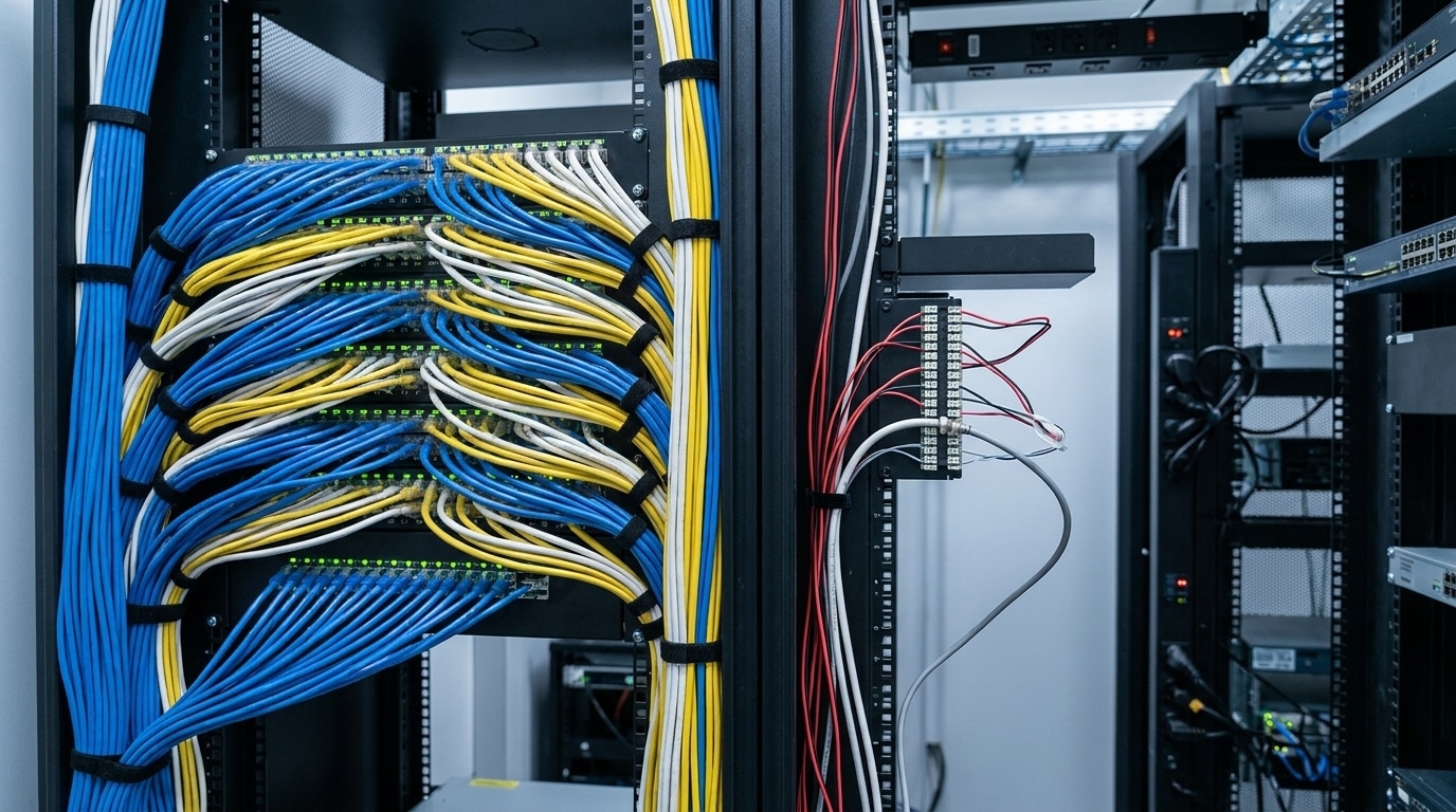
Understanding the Core Relationship: Low-Voltage Cabling vs Structured Cabling
Deploying a commercial communications network requires balancing immediate equipment electrical limits with long-term data pathway organization. While low voltage refers to the specific physical media and electrical capacity of the wiring, structured cabling describes the broader engineering design. One defines the material properties of the wire, while the other defines how those wires form a functional, manageable network.
- Physical Medium (Low-Voltage Cabling): The actual wiring materials, such as Cat6, fiber optic, or coaxial cables, that operate at 50V or less.
- Architectural Design (Structured Cabling): The standardized engineering framework (TIA/EIA-568) that organizes these physical wires into a cohesive, manageable network.
- Functional Application: Low-voltage systems supply targeted power and simple connectivity to edge devices, while structured setups provide the scalable central backbone for all voice, video, and data traffic.
| Feature | Basic Low-Voltage Wiring | Structured Cabling System |
| Core Focus | Point-to-point connections for individual devices | Centralized, standardized architecture for the entire building |
| Standards Compliance | NEC Articles 725 and 800 (electrical safety only) | ANSI/TIA-568-E, ISO/IEC 11801 (performance and testing) |
| Pathways & Organization | Ad-hoc routing, often unsupported or grouped informally | Dedicated conduits, trays, J-hooks, and structured patch panels |
| Scalability | Low; requires running new lines for device upgrades | High; modular design allows plug-and-play equipment swaps |
| Troubleshooting | High complexity; time-consuming manual tracing of wire runs | Low complexity; fast tracing via color-coded, labeled patch points |
What Is Low-Voltage Cabling?
Low-voltage cabling refers to electrical systems that operate at 50 volts or less, which is significantly lower than standard lighting or outlet circuits. Common voltage levels in these systems include 12V, 24V, and 48V. The National Electrical Code categorizes these as Class 2 and Class 3 circuits, designed primarily to carry signals and data rather than heavy power loads.
These systems utilize various media types to transmit voice, data, and audio signals across a property. Category-rated copper cabling, such as Cat6 and Cat6a, is frequently used for high-speed internet, while fiber optics provide the speed necessary for long-distance data transmission.
Coaxial cables and audio distribution lines also fall under the low-voltage umbrella. Because these lines carry limited power, they fall under NEC Article 725 power-limited guidelines rather than the heavy overcurrent protection and conduit requirements governing high-voltage branch circuits.
Limiting the power supply or current levels based on specific designations maintains the safe operation of these circuits. For Class 2 circuits operating at 30V or less, the power supply is limited to 100VA to mitigate shock and fire hazards. Class 3 circuits allow for higher power outputs but require cables with enhanced insulation ratings to manage the load properly. Understanding these electrical thresholds helps ensure the physical layer of the building meets safety requirements without over-engineering power delivery.
What Is Structured Cabling?
Structured cabling is a holistic engineering methodology that organizes various low-voltage wires into a predictable and standardized topology. Instead of running a single wire for a single purpose, this approach creates an integrated telecommunications infrastructure that supports many different technologies. It involves a comprehensive network of hardware components, including enclosures, backbone conduits, and standardized wall jacks.
The primary goal of this architectural design is to turn isolated wire runs into a cohesive building system. By using standardized components like patch panels and main distribution frames, technicians manage the entire network from a centralized location. Centralized organization allows applications like security, voice, and data to share the same physical framework. It provides a foundation that’s both flexible and easy to document as your facility’s needs change.
The active ANSI/TIA-568-E standards govern commercial cabling installations to ensure system interoperability and maximum network performance. These standards define exactly how cables should be installed, how they should connect to hardware, and how technicians must test them. When executed correctly, a structured framework easily outlasts multiple generations of active hardware. Instead of a simple collection of wires, you gain a durable, highly organized asset.
Why the Distinction Between Low-Voltage and Structured Systems Matters for Commercial Properties
Hiring an installer to run low-voltage wire simply often results in point-to-point connections that are difficult to manage over time. These as-needed installations frequently lead to a jumbled mess of cables in ceiling spaces, often called a spaghetti pile. While these individual runs might work for a single device, they lack the organization needed for a growing enterprise. Without a structured framework, identifying which cable goes to which device becomes nearly impossible during a network outage.
A structured cabling approach creates an open-architecture system that is neutral toward specific hardware vendors. As a result, a warehouse or medical center can switch equipment brands without needing to rip out and replace all the wiring. Facilities that lack this organization face significant operational risks, including prolonged downtime during repairs. An organized physical layer is a prerequisite for any business that relies on consistent connectivity for daily operations.
Modern building design integrates various communication and control systems into a single network for better efficiency. When a facility uses a structured framework, it supports data, security, and building automation through one organized path. Consolidating these systems simplifies property management and reduces redundant wiring. It also makes it easier for facility managers to audit their systems and plan for future technology deployments.
Impact on Future-Proofing and Bandwidth Scaling
Technology cycles outpace building lifespans, making adaptable infrastructure a core requirement for commercial property valuation. Upgrading active hardware like network switches or wireless access points requires a physical layer capable of handling increased bandwidth and power loads without bottlenecking. A structured approach ensures that when a facility upgrades from 1G to 10G or even 40G network speeds, the cabling embedded in the walls and ceilings will not need to be replaced.
Structured Cabling vs Low-Voltage Wiring: Key Structural Differences
Architectural planning and regulatory compliance separate basic wiring from a structured system. Basic wiring focuses on the immediate connection of a device, while structured systems focus on the long-term health of the entire building network. Understanding these structural differences is the first step in building a reliable enterprise environment.
Point-to-Point Ad-Hoc Wiring vs Standardized Architectural Design
Point-to-point cabling is an ad-hoc solution where a direct cable runs from a source port to a specific destination device. This method is applied in the field as needed whenever a new phone, camera, or workstation is added to the facility. While this setup works for a small office with a handful of connections, it quickly becomes unmanageable as device counts grow. Without a planned deployment, tracking and maintaining individual lines turns into an operational nightmare.
By standardizing network wiring through a hierarchical star topology, facilities avoid the performance degradation common in ad-hoc installations. Horizontal cabling connects every individual work area outlet to a patch panel located in a dedicated telecommunications room. This design separates the permanent building infrastructure from the flexible patch cables used to connect equipment. This separation ensures that system changes remain clean and don’t disturb the main wiring behind the walls.
A jumbled mess of unorganized cables can cause costly delays during installation or when something goes wrong. Too many direct fiber or copper runs without a plan will eventually interfere with airflow and access in equipment rooms. A planned cabling system systematically lays out the management necessary for voice, data, and video. Proper planning prevents the buildup of abandoned cables and keeps the building’s pathways clear for future use.
Adherence to Telecom Standards (ANSI/TIA-568 & ISO/IEC 11801)
Basic low-voltage wiring is primarily governed by electrical safety codes that prevent fires and shocks. Structured cabling goes much further by complying with rigorous performance standards like ANSI/TIA-568 and ISO/IEC 11801. These specifications ensure the network can handle high-speed data throughput, such as 10Gbps, without signal loss. Following these rules guarantees that hardware from different manufacturers will work together seamlessly on the same network.
The ANSI/TIA-568-E standards specify mechanical and transmission parameters down to exact physical tolerances. They define strict bend radius limits (typically four times the cable’s outer diameter for copper) to prevent physical attenuation, and establish precise performance thresholds for Near-End Crosstalk and Return Loss to prevent electromagnetic interference. If a cable is pulled too tightly or twisted incorrectly during installation, it may fail to meet these certification requirements. By sticking to these specs, business owners ensure their infrastructure is prepared for modern bandwidth demands.
Using standards-compliant systems also simplifies the testing process for the entire network. Technicians use specialized Level V field testers to measure cable parameters and certify that each channel meets its rated performance class. This certification provides documented proof of bandwidth capacity before active switches are deployed, shielding business owners from post-installation troubleshooting costs. Without these standards, there’s no guarantee that a newly installed wire will actually support the speed required by the business.
Physical Organization, Labeling, and Documentation Standards
Organization in a structured system requires every cable to be labeled at both ends with a unique identifier. In accordance with the active ANSI/TIA-606-C administration standard, all telecommunications infrastructure labels must be mechanically printed and highly durable. Every identifier on a wall jack or patch panel must correspond to a specific entry in the building’s documentation database. Rigorous labeling eliminates the guesswork that usually accompanies unorganized wiring systems.
Unlabeled patch panels often turn a simple network change into a frustrating scavenger hunt for IT staff. There are cases where technicians spent two full days tracing lines on an unlabeled 48-port panel before an upgrade could even begin. In a structured system, organized cable trays and J-hooks keep wires supported and out of the way. This arrangement allows for better airflow and easier access to other building components like heating, ventilation, and air conditioning ducts.
Proper documentation also includes a complete map of the cable routing throughout the facility. When cables disappear into plenum ceiling spaces without a map, they become “lost” to future generations of IT personnel. Strict adherence to standards like NEC Article 800.25 requires the removal of abandoned, non-plenum-rated communications cables to prevent toxic smoke hazards and comply with local commercial building codes. Having a clear record of every active line makes it easy to comply with these safety codes and keep the facility organized.
The Six Functional Subsystems of Enterprise Structured Cabling Systems
Implementing enterprise cabling systems requires a deep understanding of the six functional subsystems defined by TIA standards. These building blocks work together to ensure that data flows smoothly from the outside world to every desk in the facility. By breaking the system down into these areas, engineers can design a network that’s both efficient and easy to troubleshoot.
Entrance Facilities and Equipment Rooms
The entrance facility acts as the official demarcation point where external carrier-class networks hand off their lines to the building. This designated space houses overvoltage protection devices and pathway penetrations that transition outside plant cabling to interior-grade media.
The equipment room houses core network servers and the main cross-connect while maintaining dedicated HVAC environmental controls, typically holding 64°F to 75°F with 8% to 60% relative humidity per ASHRAE guidelines, to protect sensitive hardware. Proper design in this room includes dedicated power supplies and enough rack space to handle future hardware growth. Investing in a well-organized equipment room provides a secure and reliable home for your business’s most valuable technology.
Telecommunications Rooms and Riser/Backbone Cabling
Telecommunications rooms are intermediate points located on different floors of a large building. These rooms house the patch panels and edge switches that connect specific sections of the facility to the main hub. Because ANSI/TIA standards restrict horizontal copper cable runs to a maximum permanent link distance of 90 meters (295 feet) from the patch panel, expansive facility layouts or multi-story structures require strategically placed TRs on each floor. They act as a local distribution point for the workforce on that specific floor.
Backbone cabling links the main equipment room to each of the Telecommunications Rooms. In modern installations, this backbone is almost always made of multimode or singlemode fiber optic cables. These lines handle heavy aggregated traffic from multiple users and must support exceptional speeds. Backbone systems often span several floors or even multiple buildings in a campus environment.
The ANSI/TIA-568-E standard establishes strict distance limits for backbone runs to preserve signal integrity. Multimode fiber is typically limited to 2,000 meters for backbone distribution, while single-mode fiber can extend up to 3,000 meters or more depending on the network classification and active transceivers. These long-distance links allow a business to function as one unified network across an entire property. Without a strong backbone, communication between different departments or floors becomes slow and unreliable.
Horizontal Cabling and Work Areas
Horizontal cabling runs from the telecommunications room patch panels to individual outlets on the floor, traditionally limited to a maximum permanent link distance of 90 meters to preserve signal strength. The work area comprises the end-user equipment, such as desktop PCs, Wi-Fi access points, and VoIP phones, along with the patch cords connecting them to the telecommunications outlet.
What Systems Rely on Low-Voltage and Structured Cabling Frameworks?
Modern businesses use a wide variety of technologies that all depend on the same physical infrastructure. From the phones on the desks to the lights in the ceiling, the cabling system handles both data and power delivery. Integrating these various systems into one framework makes them easier to manage and more reliable. This integration remains the standard for high-density commercial spaces.
Voice, High-Speed Data, and Enterprise LAN Networks
Enterprise Local Area Networks and high-speed Wi-Fi systems are the most common users of a building’s cabling. These networks rely on Category 6 or Category 6A copper runs to handle high-bandwidth applications. While Cat6 supports 1 Gbps data rates at the standard 100-meter channel limit, Cat6a is engineered to handle 10 Gbps speeds at a full 100 meters. It operates at frequencies up to 500 MHz, effectively neutralizing the crosstalk bottlenecks that disrupt legacy Cat5e infrastructures.
Under the IEEE 802.3bt Type 4 standard, PoE switches deliver up to 90 watts of DC power alongside high-speed data. In high-density environments, routing this high-wattage power requires specific bundle size limits and temperature derating considerations under NEC Article 725.144 to prevent heat buildup inside closed conduits. Delivering power through data cables lets VoIP phones and wireless access points function without a separate electrical outlet. It simplifies the installation of hardware in hard-to-reach places like high ceilings or outdoor walls.
Building Automation, Smart Lighting, and HVAC Control
Building Automation Systems use a network of low-voltage sensors to manage HVAC, lighting, and environmental controls. These systems let facility managers monitor real-time building performance and instantly optimize energy consumption. These systems are governed by NEC Article 725 for safety, with fire alarm components integrating into the backbone under strict NFPA 72 regulations. By connecting these controls to the structured cabling backbone, the facility automates maintenance triggers and responds to occupancy levels.
Smart LED lighting is another application that has embraced low-voltage infrastructure. PoE-powered lighting systems use network cables to deliver power and control signals to every fixture in the building. While these smart technologies provide immediate utility, their long-term value is only realized through a cabling strategy that prioritizes return on investment and maintenance. An integrated system provides greater control over your facility’s operational costs.
Long-Term ROI: Evaluating Costs, Scalability, and Maintenance
Evaluating a cabling project requires looking beyond the initial installation price. While basic wiring might seem cheaper at first, the long-term costs of managing an unorganized system are substantial. Evaluating the total cost of ownership over twenty years often reveals that structured cabling is the more economical choice. It’s an investment in the building’s long-term operational health.
Troubleshooting Speed and Minimizing Network Downtime
Network outages are highly disruptive, with industry research from ITIC indicating that over 90% of midsize and large enterprises experience downtime costs exceeding $300,000 per hour. Furthermore, data from LogicMonitor shows that 96% of global IT decision-makers have experienced at least one major outage over three years, making rapid fault isolation an operational necessity. When an unorganized low-voltage setup fails, pinpointing the exact location of the problem is extraordinarily difficult. Technicians often spend hours tracing unidentified lines behind drywall or in cluttered ceiling spaces.
A structured system allows IT teams to isolate faults almost instantly through clear labeling and patch panel mapping. Since every link has been tested and certified, technicians quickly rule out the permanent wiring and focus on common failure points. Patch cords are the most frequent cause of bad drops and can be replaced in seconds. Having a systematic way to identify and fix problems directly protects your company’s profitability.
Scalability and Reduced Cost of Moves, Adds, and Changes
In a standard low-voltage installation, reconfiguring an office layout or adding a new workstation requires pulling an entirely new dedicated cable from the server closet, which adds labor and disruptiveness. With a structured cabling system, modifications are made at the patch panel or consolidation point using modular patch cords. This design decreases the time and cost associated with moves, adds, and changes, reducing long-term IT operational expenditures.
How to Choose the Right Cabling Strategy for Your Facility
Choosing the right strategy depends on the size of the building and the technological needs of your business. Decision-makers should look at their long-term growth plans rather than just their immediate requirements. Partnering with certified experts ensures your facility remains competitive for years to come.
The Role of Certified Electrical Contractors and Cabling Specialists
In Florida, structured cabling and low-voltage installations are regulated by the Electrical Contractors Licensing Board. While some providers hold only a restricted Limited Energy Systems Specialty credential, Suncoast Power is a fully licensed Certified Electrical Contractor (EC13015089). This unlimited EC licensing enables our team to manage both high-voltage electrical distribution and complex low-voltage communication systems under a single, comprehensive regulatory umbrella. Hiring a licensed contractor ensures the work meets all legal requirements and safety standards.
Professional installers use specialized equipment to test and certify every copper and fiber link in the system. They ensure that communications circuits follow NEC Article 800 for proper support and safety. Without this professional certification, a business has no proof that its network will actually perform at its rated speed. Partnering with experts is the most reliable way to design a cabling system that meets your specific operational needs.
Optimize Your Cabling Infrastructure with Suncoast Power
Building a robust network requires more than just pulling wire through a ceiling. While basic low-voltage wiring provides the simple physical current needed for data, structured cabling delivers the organized architecture modern businesses require. This standardized approach ensures your facility is ready for long-term scalability and maintains low operational costs. By investing in a certified system, you protect your network from the risks of downtime and unorganized maintenance.
Suncoast Power has over 40 years of experience as a premier commercial electrical contractor in Tampa. We specialize in delivering scalable infrastructure, including enterprise structured cabling and low-voltage wiring across Florida. Our technicians handle everything from high-density fiber backbones to smart building automation systems with a focus on quality. Contact us today to schedule a comprehensive infrastructure assessment for your Central Florida property and design a cabling system that supports your operational goals.