


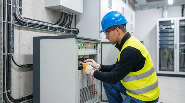


Under the 2023 National Fire Protection Association 70B mandate, implementing standardized infrared thermography protocols for high-density switchgear systems is required to maintain power stability. For over 30 years, our team at Suncoast Power has helped Florida facilities navigate these standards to avoid the failures caused by continuous thermal stress.
Chief engineers and facility managers must manage specific safety frameworks and temperature differential calculations to protect their electrical infrastructure from damage. Mastering these standardized maintenance steps is the first defense against the thermal stress that leads to catastrophic power failure.
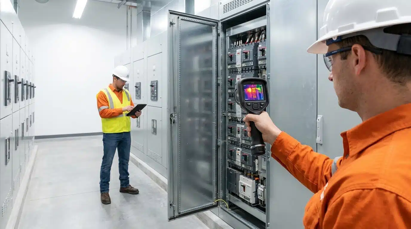
The Critical Role of Thermography in High-Density Electrical Infrastructure
High-density electrical switchgear requires specialized thermographic inspection protocols because continuous thermal stress behaves differently than in standard electrical panels. A structured inspection protocol identifies subtle heat signatures, classifying a temperature rise of 4°C to 15°C between similar components under similar loading as a probable deficiency, and any rise exceeding 15°C as a major discrepancy requiring immediate action.
Improper maintenance can increase the fault clearing time of an overcurrent protective device. The resulting delay in fault clearing time is directly proportional to incident energy, creating a significant risk for the facility and its occupants. Following a proactive testing schedule ensures that equipment operates within safe National Electrical Manufacturers Association-rated tolerances.
Compliance Mandates Under NFPA 70B and NETA Standards
In 2023, NFPA 70B transitioned from a recommended practice to a mandatory standard for all energized electrical equipment. Ensuring compliance for commercial switchgear now requires facility owners to document a formal electrical maintenance program. Under NFPA 70B Chapter 9, maintenance intervals are dictated by equipment physical condition: Condition 1 (Section 9.3.1.1) and Condition 2 (Section 9.3.1.2) mandate inspections at least every 12 months, whereas Condition 3 (Section 9.3.1.3) requires thermographic scans at least every 6 months. Equipment is assigned to Condition 3 if it has missed two successive maintenance cycles, has active unaddressed alarms, or displays urgent issues requiring immediate repair.
American National Standards Institute and International Electrical Testing Association standards further define the specific testing procedures and evaluation criteria for these power distribution systems. Many insurance companies require an electrical maintenance plan to qualify for coverage or offer lower policy premiums based on maintenance status.
Operational Hazards in Continuous-Load Hospitality and Gaming Environments
Based on Suncoast Power’s three decades of experience servicing Florida’s highly humid coastal environments, the combination of high ambient humidity and non-linear loads in gaming facilities and airport terminals significantly accelerates busbar oxidation. These non-linear loads induce elevated harmonic distortion (specifically 3rd, 9th, and 15th triplen harmonics) that overloads neutral conductors. At the same time, the humid salt air speeds up corrosion at bolted joints, rapidly escalating minor contact resistance into catastrophic thermal failure under continuous load.
Non-linear loads (such as LED lighting arrays, variable frequency drives, and heavy server infrastructure) draw current in discontinuous pulses, causing harmonic currents to add up in the neutral conductor. Because standard neutrals are often not oversized, this current summation generates severe heat stress on neutral busbar joints and conductor terminations.
Unplanned outages in these environments often result in financial consequences, including premium-time labor costs and expedited equipment replacement fees. Foregoing regular maintenance increases the risk of equipment failures and creates hazards for nearby workers.
Pre-Survey Safety Protocols and Inspection Preparation
Safety and systematic preparation are mandatory prerequisites before conducting any energized thermographic inspection on high-density switchgear. Technicians must conduct a formal Job Hazard Analysis and hold a pre-job safety briefing to coordinate actions and verify equipment integrity. Qualified personnel must establish and clearly mark the arc flash and limited approach boundaries based on the system’s incident energy analysis to prevent unauthorized entry during the survey.
NFPA 70E Arc Flash Safety and Personal Protective Equipment
NFPA 70E specifies the safety requirements for inspecting energized switchgear systems to prevent injury from electrical hazards. Technicians must perform arc flash risk assessments before beginning the energized equipment inspection. This establishes the necessary distance and precautions required for safe testing under load.
Inspectors must wear arc-rated personal protective equipment matching the specific hazard risk category determined by the arc flash label, ranging from Category 2 up to Category 4 suits with arc-rated hoods, along with insulated voltage-rated gloves. While NFPA 70B Section 7.4.2 requires removing covers to maintain a direct line of sight to bolted connections, doing so on fully energized switchgear represents the highest arc flash risk, necessitating strict adherence to NFPA 70E PPE guidelines.
Utilizing IR Windows for Closed-Door Energized Inspections
Installing calcium fluoride or polymer-based infrared windows in switchgear cubicle doors provides massive safety and operational benefits. These windows allow technicians to capture accurate thermographic data while keeping the enclosure doors fully closed and latched. This eliminates the risk of an arc flash triggered by cover removal or accidental contact, dropping the PPE requirement to basic daily wear during the actual scan.
Using IR windows supports safer, faster, and more repeatable inspections compared to traditional open-panel methods. Because panels remain closed, teams can complete inspections more quickly and with less disruption to the facility. Consequently, technicians can focus more effectively on specific components of interest during peak load periods.
These windows are particularly beneficial for equipment that requires monitoring every six months due to its physical condition. They provide a guarded condition that keeps the system energized and protected while the scan is performed.
Step-by-Step Execution Protocol for Energized Switchgear Thermal Surveys
Executing an accurate thermal survey on high-density commercial switchgear requires a meticulous, standardized sequence to isolate true thermal anomalies from background reflections. Qualified personnel must follow this five-step energized equipment inspection process:
- Verify System Load: Ensure the system operates under a minimum of 40% of nominal circuit load (and ideally maximum normal load) in accordance with NFPA 70B Section 7.4.5, allowing high-resistance connections to generate detectable heat.
- Compensate for Emissivity: Calibrate the thermal imager’s emissivity settings based on the target materials (e.g., 0.95 for painted surfaces, 0.30 to 0.50 for oxidized copper or aluminum busbars, and 0.10 for shiny metal).
- Perform Background Correction: Measure and input the reflected temperature correction to eliminate errors caused by hot components or ambient lighting reflecting off shiny metallic components.
- Capture Co-aligned Images: Record simultaneous, side-by-side visual and thermal images of each component under test, ensuring exact alignment to assist with subsequent mechanical localization.
- Perform Delta-T Calculations: Measure the temperature difference between the target component and a similar phase under identical load (component-to-component) or the surrounding ambient air (component-to-ambient).
Minimum Operating Load Requirements and System Stabilization
Because resistive heating scales quadratically with current, low circuit loads generate negligible heat, hiding severe mechanical faults. NFPA 70B Section 7.4.5 dictates a minimum load of 40% of nominal capacity during the scan; however, surveys should ideally be scheduled during peak operational load periods to maximize thermal contrast at high-resistance points. Technicians must also verify that the system has reached thermal equilibrium, requiring a stabilization period of at least one hour following any major load adjustment before capturing measurements.
Inspections performed at low load levels often fail to reveal high-resistance joints that only become problematic at higher currents. Technicians must document the load conditions at the time of the inspection to provide context for the results. Without sufficient load, a thermal imager cannot effectively identify the defects that lead to equipment failure.
Calibrating Equipment for Accurate Switchgear Thermography Protocols
Selecting the correct emissivity is critical: scanning a shiny, unpainted brass lug with the camera set to a default painted-surface emissivity will result in a severely underestimated temperature reading, potentially masking a critical fault. For reliable diagnostics, the thermal imager must meet strict performance parameters: a Noise Equivalent Temperature Difference of 0.05°C to resolve subtle heat variations, and a minimum optical resolution of 320 x 240 pixels to capture small, high-density terminations from a safe distance clearly
Technicians must use target-specific emissivity values or apply high-emissivity electrical tape (rated for the equipment’s operating temperature) to bare metal contact points to establish a uniform measurement surface. Additionally, they must actively correct for reflected temperature by shielding the target from external heat sources or calculating background reflections via standard infrared window correction formulas.
Temperature Differential Analysis and Load Compensation
Quantitative temperature differential analysis removes subjectivity from thermal scans by establishing clear action thresholds based on measured heat rises. By comparing a compromised component’s temperature directly to an adjacent, identical phase operating under the same load (component-to-component) or to the surrounding ambient air (component-to-ambient), facility engineers can pinpoint high-risk terminations.
Applying the Square Law for Ambient and Load Correction
Because heat energy generated by electrical resistance is proportional to the square of the current, a minor temperature rise detected at a lower operating load can escalate exponentially at peak demand. To prevent underestimating fault severity, technicians must normalize the measured temperature rise to the rated load current using the square law formula. Normalizing these values prevents critical high-resistance connections from being overlooked when inspections occur during low-demand cycles.
Severity Classification and Risk Prioritization Matrices
NETA Table 100.18 provides specific severity criteria that facility engineers use to establish response timelines. A major discrepancy indicates a severe temperature differential and requires an immediate repair to prevent failure. These classifications help prioritize maintenance efforts in complex, high-density environments.
To systematically prioritize maintenance resources, technicians evaluate results using the ANSI/NETA Maintenance Testing Specifications Table 100.18:
| ΔT between Similar Components (Similar Load) | ΔT between Component and Ambient Air | Severity Class & Recommended Action |
| 1°C to 3°C | 1°C to 10°C | Possible deficiency; warrants further investigation. |
| 4°C to 15°C | 11°C to 20°C | Indicates probable deficiency; repair as time permits. |
| N/A | 21°C to 40°C | Monitor closely until corrective measures can be made. |
| >15°C | >40°C | Major discrepancy; requires immediate repair or isolation. |
Common Thermal Anomalies Identified During an Electrical Panel Thermal Scan
Identifying the physical and electrical causes of thermal abnormalities is the primary goal of any thermographic survey. Most problems found in high-density switchgear can be traced back to mechanical failures or electrical imbalances. Infrared thermography serves as a powerful diagnostic tool for identifying hidden defects.
Analyzing these precise heat patterns allows technicians to locate hidden physical defects before they trigger unexpected power outages.
High-Resistance Busbar Connections and Termination Failures
High-resistance busbar connections are often caused by improper torque, mechanical vibration, or surface oxidation. These factors create micro-gaps that increase resistance and generate localized heat at the point of connection. Thermal expansion cycles can further exacerbate these issues over time by loosening bolted joints.
During an electrical panel thermal scan, a high-resistance termination displays a highly localized, high-temperature spot at the point of contact, with temperature dropping rapidly along the conductor (known as a conduction-cooled profile). This distinctive thermal signature immediately distinguishes a mechanical connection failure from a generic circuit overload, which exhibits uniform heating along the entire length of the conductor.
Early detection of these high-resistance hot spots prevents thermal runaway, which can melt busbar insulation and trigger a phase-to-phase short or devastating arc flash. Under NFPA 70B, verifying bolted bus connections via thermography is a mandatory safety defense. Regular scans identify hardware that has loosened due to thermal cycling and copper creep before contact failure occurs.
Circuit Breaker Overloading, Harmonics, and Phase Imbalances
Phase current imbalances and harmonic distortion create systemic thermal stress across the entire switchgear assembly. In systems with high non-linear loads, triplen harmonics (primarily the 3rd harmonic and its odd multiples) do not cancel out in the neutral; instead, they add up in the common neutral conductor, driving the neutral current to as high as 1.73 times the phase current and causing severe heating in the neutral busbar.
To accurately diagnose the root cause, technicians must use a clamp-on power quality analyzer alongside the thermal camera. If the thermal scan shows a hot phase conductor but current measurements are balanced, the issue is high contact resistance (such as a loose lug). If current measurements are unbalanced, the issue is phase load distribution. This diagnostic crossover prevents facility managers from wastefully retorquing connections when the true fix requires load rebalancing.
Infrared thermography is a valuable tool for detecting the effects of destructive harmonics in modern buildings. Since many of these effects involve overheating, a thermal scan can reveal issues that might not be apparent through other testing methods. Understanding these dynamic electrical stressors is essential for managing high-density switchgear.
Data Documentation and Reporting Standards for Maintenance Action
Thorough documentation and structured reporting are essential to translate thermal survey findings into effective corrective maintenance. Without a clear record of the results, the value of the thermographic inspection is significantly diminished. Accurate reporting helps facility managers track the health of their equipment over time.
Under NFPA 70B Chapter 30, thermographic survey records must be maintained as part of the facility’s permanent Electrical Maintenance Program files. These reports serve as verifiable proof of compliance during OSHA inspections, defend against insurance liability claims, and provide the exact temperature data required to refine incident energy calculations in ongoing safety audits.
Essential Elements of NFPA 70B Compliant Thermal Reports
An NFPA 70B compliant thermographic report must contain highly structured data to allow facility managers to take immediate corrective action. Under NFPA 70B and NETA standards, every report must include:
- Side-by-Side Imagery: High-resolution thermograms co-aligned with matching digital visual photographs for every identified thermal discrepancy.
- Equipment Metadata: Unique equipment identification tags (such as asset ID numbers), precise physical locations, and exact component descriptions.
- Environmental & Load Data: Ambient air temperature, relative humidity, wind speed (for outdoor switchyards), and the exact operating load percentage (with phase currents) at the time of the scan.
- Thermal Calculations: Recorded temperatures of the fault, reference components, and the resulting component-to-component or component-to-ambient temperature differential.
- Diagnostics & Repair Priority: Probable cause of the thermal anomaly, NETA severity ranking, recommended corrective actions, and the certification level of the technician performing the survey.
Establishing Condition-Based Maintenance Schedules and Baseline Trending
Facility engineers use thermographic survey reports to transition from reactive maintenance to a condition-based predictive program. By tracking historical temperature differentials for critical switchgear over multiple cycles under normalized loads, maintenance teams can identify early-stage degradation. If a connection’s normalized ΔT rises steadily from 2°C to 12°C over three consecutive scans, engineers can schedule repair during planned downtime before it escalates to a major discrepancy.
Integrating regular thermal scans with the facility’s overall EMP ensures compliance with local municipal codes and NFPA standards while maximizing equipment life. Rather than executing blanket annual maintenance, tracking these subtle thermal anomalies allows engineers to deploy resources specifically to at-risk switchgear assemblies, reducing overall operational costs.
Trending analysis helps identify components that may be aging prematurely due to environmental factors or load stress. It also provides a way to verify that past repairs were effective in resolving the original thermal issues. A condition-based program is the most efficient way to manage high-density electrical infrastructure.
Contact Suncoast Power Today To Schedule Your On-Site Assessment
Standardized infrared thermography is an essential operational strategy for high-density Florida facilities, representing far more than a simple regulatory compliance task. In mission-critical hospitality, gaming, and aviation terminals, mitigating continuous thermal stress via structured thermographic inspection is the most effective way to protect personnel and ensure long-term power stability.
At Suncoast Power, our Level II and III certified thermographers provide the specialized expertise required to navigate these safety mandates. We help commercial, industrial, and hospitality facilities across Florida build robust, NFPA 70B-compliant electrical maintenance programs. Contact us today to schedule your on-site assessment and thermal survey today.