




A reliable low-voltage wiring layout for commercial security systems is a strategically engineered network of Class 2 or Class 3 power-limited circuits that connect sensors, cameras, and access points to a centralized management hub. For facility managers and IT directors, a well-designed cabling architecture ensures that hardware operates without signal loss or power interruptions. Designing high-performance security infrastructure requires strict adherence to National Electrical Code Article 725 and established structured cabling topologies to prevent costly system failures.
Technical failures often stem from poor infrastructure rather than the hardware itself. Inferior layouts frequently lead to dropped video frames, intermittent lockouts in access control systems, and frequent false alarms. Strict adherence to cable selection, regulatory codes, distance limitations, and Power over Ethernet budgets keeps your security network stable and compliant.
What Makes Low-Voltage Wiring Critical for Commercial Physical Security Systems?
Commercial facilities demand constant uptime. A professional low-voltage security installation ensures that edge devices such as IP cameras and credential readers operate on dedicated pathways, maintaining direct communication with centralized management servers without bottlenecking local network switches.
The Difference Between High-Voltage Power and Low-Voltage Security Wiring
Standard line-voltage electrical systems typically operate between 120V and 480V, presenting significant shock hazards that necessitate heavy conduit and strict physical isolation. By contrast, low-voltage wiring utilizes an electrical potential of 50 volts or less, drastically reducing fire risks and permitting flexible routing throughout the plenum space without bulky conduit.
Security systems commonly utilize 12 VDC, 24 VDC, or 48 VDC for control signals and device power. These circuits function as the sensory nervous system of a facility, carrying data packet streams and low-power electrical triggers. These systems carry less energy and avoid the heavy conduit requirements of high-voltage branch circuits.
Core Components of Commercial Physical Security Infrastructure
Primary security sub-systems like IP surveillance networks and door access control systems depend entirely on the underlying low-voltage layout. Intrusion detection alarms and centralized management servers also require dedicated paths to communicate with the rest of the facility. These systems interact through a complex web of network switches, access control panels, and specialized power supplies.
A failure in any part of the wiring layout compromises the operational integrity of the entire physical security framework. If a cable run to a door controller fails, the entire entry point may become unsecured or inaccessible. Proper layout design ensures that these distinct systems can exchange data without interference or signal loss.
Integrated devices, such as the Bosch DS160 request-to-exit detectors, often feature built-in sounders and sensors that require specific conductor counts. These detectors can be programmed to alert staff if a door remains open for an extended period.
Integrating Physical Security with Building Automation
Standalone security endpoints leave critical data isolated. Tying low-voltage security circuits into a broader building automation system allows facility managers to program intelligent trigger events across multiple platforms.
For example, an integrated access control swipe can automatically adjust the localized HVAC zone and trigger customized lighting scenes. This cross-system communication requires centralized structured cabling drops that bridge physical security hardware and primary environmental control servers.
Key Cabling Standards and Regulatory Compliance for Commercial Security Layouts
Commercial installations must adhere to national electrical safety codes and structured cabling standards. Compliance ensures fire safety, signal performance, and legal protection during building inspections. Standardized engineering practices provide a clear framework for contractor deliverables and long-term system stability.
Understanding NEC Article 725 and Class 2/3 Power-Limited Circuits
The National Electrical Code governs low-voltage circuits through Article 725, which defines the requirements for power-limited and remote-control circuits. Class 2 circuits are the standard for most security applications because they limit power output to prevent electric shock and fire hazards. Designers must choose the correct class based on the power requirements of the endpoint hardware.
NEC Article 725 Classifications: At a Glance:
- Class 2 Circuits: Typically operate at up to 30V with a strict power limit of 100 VA. Because they pose minimal shock or fire hazard, they are the standard for most access control controllers and IP cameras.
- Class 3 Circuits: Designed for equipment requiring higher power levels, operating up to 100V (or 150V under specific conditions) with a 100 VA to 1000 VA power limit.
- CL3 Cable: Rated for up to 300V, CL3 jacketed cables are mandatory for Class 3 circuits to prevent insulation breakdown under higher load conditions.
Maintaining strict code compliance during the initial pathway design prevents costly building inspection failures. If a system is installed using the wrong cable class, a building inspector may mandate a total teardown and reinstallation. Following Article 725 guidelines ensures the installation is safe and permanent.
Plenum vs. Riser Ratings for Commercial Security Pathways
Communications Plenum cables feature low-smoke, flame-retardant jackets designed for use in air-handling spaces. These areas, such as the space above a suspended ceiling or below a raised floor, move environmental air throughout a building. National Fire Protection Association codes mandate plenum-rated cables in these zones to prevent the spread of toxic smoke during a fire.
Communications Riser cables are engineered to resist vertical flame propagation between floors. These are used in non-air-handling shafts where cables must pass through floor penetrations. While CMR is suitable for vertical runs, it lacks the smoke-suppression qualities required for horizontal air-handling spaces.
Choosing the correct jacket type is a primary safety consideration for any commercial security wiring project. Using riser-rated cable in a plenum space is a major code violation and a significant safety risk. Designers must verify the environmental status of every pathway before selecting the cable stock.
ANSI/TIA-568 and BICSI Standards for Security Cable Architecture
Industry professionals rely on the ANSI/TIA-568 cabling standard and BICSI design manuals to ensure robust network performance. These standards define the precise electrical parameters, return loss, and crosstalk limits for Category 5e, 6, and 6A channels, guaranteeing the infrastructure can support the high bandwidth of modern IP surveillance networks.
Structured cabling principles dictate a maximum total channel length of 100 meters for copper wiring. This channel typically consists of 90 meters of horizontal solid conductor cable and 10 meters of flexible patch cabling. Exceeding these limits leads to signal attenuation and data loss that compromises video quality.
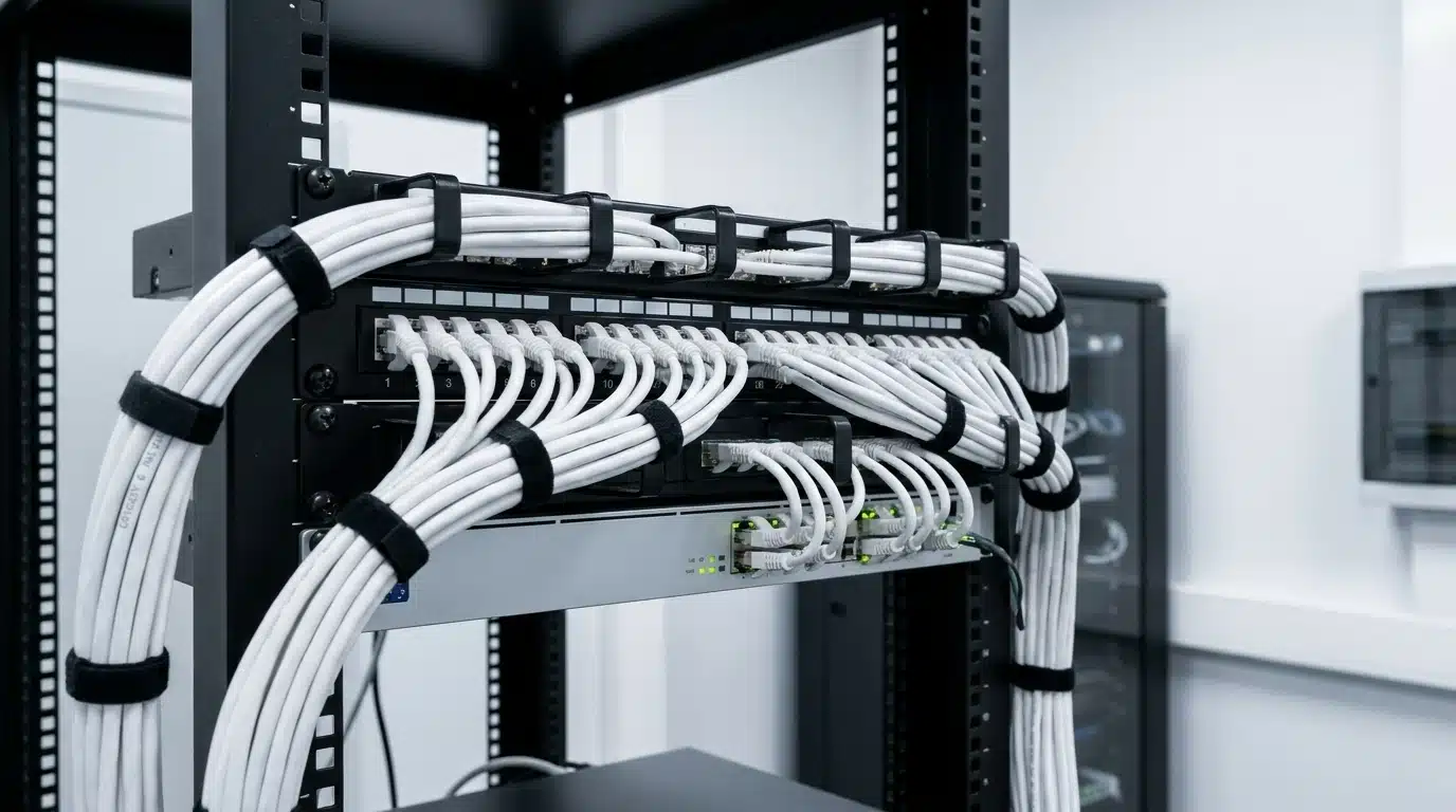
Implementing these engineering standards provides a clear framework for contractor deliverables. It ensures that every cable is terminated at a patch panel and labeled according to a standardized convention. This organized approach simplifies long-term maintenance and makes future system expansions much easier to manage.
Selecting High-Performance Access Control Cabling and IP Camera Wiring
Matching specific cable categories to hardware endpoints is critical for the long-term stability of a security system. Each device type has unique requirements for bandwidth, power delivery, and signal protection. Technicians must evaluate the specific environmental conditions to prevent interference and signal loss.
Twisted Pair Ethernet Cables (Cat6 vs. Cat6A) for IP Cameras and PoE Switches
| Parameter | Category 6 (Cat6) | Category 6 Augmented (Cat6A) |
| Max Data Rate (at 100m) | 1 Gbps | 10 Gbps |
| Bandwidth / Frequency | 250 MHz | 500 MHz |
| Conductor Size (Typical) | 24 AWG | 23 AWG |
| PoE Performance (Heat Dissipation) | Moderate (higher resistance) | Excellent (lower resistance) |
| Shielding (Alien Crosstalk) | Standard (susceptible in tight bundles) | Superior (splines or shielding) |
While standard Cat6 is sufficient for basic access control endpoints, Cat6A is the engineering standard for high-resolution 4K IP security cameras, especially when bundled tightly in cable trays where alien crosstalk and PoE heat build-up are major concerns.
The larger 23 AWG conductors in Cat6A offer lower DC resistance than the 24 AWG conductors found in Cat6. This leads to less heat generation and better thermal headroom when cables are tightly bundled. Superior thermal management is especially important for high-wattage Power over Ethernet applications like motorized pan-tilt-zoom cameras.
Multi-Conductor Shielded Cabling for Access Control Locks and Readers
Reliable access control cabling frequently utilizes multi-element composite cables (often referred to as “banana cables”) that bundle multiple distinct cable runs within a single overjacket. A typical four-element composite cable includes an 18/4 stranded conductor for electrified locks (providing 1600 lbs of holding force), a 22/6 shielded conductor for smart readers supporting secure Open Supervised Device Protocol communications, a 22/2 conductor for request-to-exit motion sensors, and a 22/4 conductor for door contacts.
Auxiliary components like request-to-exit sensors and door position switches generally use 22/2 conductors. Overall shielding with a dedicated drain wire is essential for these runs to prevent signal degradation. Without shielding, electromagnetic noise from nearby electrical systems can cause readers to fail or locks to trigger unexpectedly.
Using stranded copper conductors ensures that the wiring remains flexible enough to move through door frames and hinges. Low-voltage control and data cables should be terminated using terminal strips with crimp-type lugs. This method provides a more secure connection than wire nuts or basic crimp connectors.
Fiber Optic Backbones for Extended Distance Security Network Runs
Fiber optic cabling is necessary when security network runs must exceed the 100-meter limit of copper wiring. Fiber optic cabling transmits high-definition video signals over distances exceeding several miles. Unlike copper, fiber optic lines are immune to electromagnetic interference and signal attenuation over long distances.
The link attenuation allowance for an optical fiber run is calculated by totaling the cable loss, connector insertion loss, and splice loss. Maximum mated fiber pair connector loss is generally limited to 0.75 dB per pair. Tight loss tolerances ensure that high-definition video signals remain crisp even when transmitted across a massive campus.
Integrating fiber backbones allows for centralized head-end management across massive physical footprints, such as expansive industrial warehouses or multi-building corporate campuses. In these layouts, localized media converters or PoE-enabled edge switches convert the optical signal back to copper, enabling standard IP cameras to function far beyond the traditional 100-meter copper limit.
Engineering Standards for a Commercial Security Wiring Layout
A successful security layout requires proactive planning and a deep understanding of electrical interference. Precise calculations and physical separation of conduits are the only ways to ensure system reliability. Adhering to these standards prevents interference issues that often plague poorly planned layouts.
How to Avoid Electromagnetic Interference and High-Voltage Separation
Electromagnetic interference occurs when low-voltage signal lines are placed too close to high-voltage electrical lines. NEC Article 725 requires power-limited circuits to remain separate from higher-voltage circuits unless they are in separate conduits. Maintaining a minimum separation distance of 50 mm from high-voltage conductors is a standard industry practice.
Best practices for commercial security wiring dictate that data cables should be routed at least 12 inches away from parallel high-voltage lines. If an intersection is unavoidable, the low-voltage cable must cross the high-voltage conduit at a strict 90-degree angle. This orientation minimizes the surface area where EMI can transfer between the two systems.
EMI can induce video noise, data packet corruption, and false alarm signals in unshielded runs. By following these clearance rules, installers protect the integrity of the communication signal. This is vital in industrial settings where large motors and fluorescent lighting generate significant electrical noise.
Calculating Power Budgets and Voltage Drop for Long Cable Drops
Voltage drop is the reduction in electrical potential that occurs as current flows through a wire over a distance. This phenomenon is a major concern for 12VDC and 24VDC door locks and security cameras.
For 12VDC systems, a voltage drop exceeding 10%, or 1.2V, typically causes device failure. Systems using 24VDC offer more headroom, but technicians must still perform precise calculations. If the voltage at a magnetic lock drops too low, the hardware may fail to lock under load.
Using a thicker 18 AWG wire gauge reduces resistance and mitigates voltage drop, though extreme distances may require installing a localized power supply directly at the door.
Implementing Structured Cabling Topology (Star Network Layout)
The hierarchical star topology is the industry standard for commercial low-voltage security layouts. In this configuration, every camera, reader, or sensor has an individual home-run drop back to a centralized patch panel. This eliminates single points of failure that are common in daisy-chained or bus-style architectures.
Using a star layout simplifies troubleshooting because each device is on its own dedicated circuit. If one cable is damaged, it only affects a single device rather than taking down the entire system. A centralized star layout also enables seamless expansion, as new devices can be added without rerouting existing lines.
Centralized patch panels allow for better organization and easier management of the network. Technicians can quickly identify and test specific runs from one location within the server room. This organized approach reduces the time and labor required for future upgrades or repairs.
Designing Centralized Security Rooms and IDF/MDF Enclosures
The Main Distribution Frame and Intermediate Distribution Frames must be carefully outfitted to protect security hardware. Conduits should be a minimum of 3/4 inch trade size to accommodate cable bundles and future growth. Access control local control panels should be located within these secure rooms to prevent physical tampering.
Thermal management and ventilation prevent hardware from overheating in dense equipment racks. Proper cable tray management and the use of J-hooks spaced no more than five feet apart prevent cable sagging. Maintaining a cable bend radius of at least four times the cable diameter prevents internal damage to copper strands.
Secure access control for the rack enclosures themselves is a basic security requirement. If the infrastructure that manages the cameras is physically vulnerable, the entire security system is at risk. Ensuring that only authorized personnel can access the MDF and IDF maintains the chain of security.
How Power over Ethernet Impacts Security Cabling Architecture
Power over Ethernet technology streamlines security layouts by delivering both DC power and high-speed data over a single Category cable. However, integrating high-draw edge devices requires precise calculations of total switch power budgets and line losses.
Standard PoE (802.3af), PoE+ (802.3at), and Hi-PoE (802.3bt) Requirements
The IEEE 802.3af standard, known as Type 1 PoE, provides up to 15.4 W of DC power per port. This is sufficient for basic IP cameras and simple credential readers. IEEE 802.3at, or PoE+, provides up to 30W and is used for advanced cameras that require more energy for processing.
Modern security hardware often requires the IEEE 802.3bt standard, which delivers up to 90W. High-draw devices like PTZ cameras with built-in heaters or active deterrence hardware rely on this high-power output. Delivering this much power over four pairs of Cat5e or Cat6A cables requires specialized heat management strategies.
A Cat 5 cable carrying 400 mA of current can experience a 10 degrees Celsius temperature increase. Using Cat 6A for high-wattage PoE results in only a six degrees Celsius rise due to its larger conductors. Auditing the switch power budget is necessary to ensure the network can handle the total wattage of all connected devices.
Overcoming the 100-Meter Distance Limit for IP Security Cameras
The 100-meter distance limitation for copper Ethernet channels is a rigid physical constraint. For large facilities, designers must use specific engineering options to extend security network drops. Long-range PoE switches and inline PoE extenders push signals further by regenerating the data and power along the run.
Media converters and ePoE technology offer alternative ways to reach distant areas of a property. These systems can transmit data over existing coaxial cable or use specialized signaling to exceed standard distances. Localized fiber-to-copper conversion nodes are also a common solution for perimeter cameras.
Planning for these distance limits early in the design phase prevents connectivity issues during installation. If a camera is placed 110 meters away without an extender, the link may appear active but will suffer from constant packet loss.
What Are Common Low Voltage Wiring Pitfalls in Commercial Security Installations?
Poorly executed wiring will crash even the most advanced security hardware. Contractors must address infrastructure support, labeling, and backup power early in the build.
Improper Cable Support and Unsecured Wire Paths
Laying cables directly on drop-ceiling tiles is a common but dangerous installation error. Security lines should never be zip-tied to electrical conduit or sprinkler pipes, as this violates fire codes. Over-tightening cable ties can pinch internal twisted pairs, leading to signal impedance and data corruption.
Code-compliant cable trays, bridle rings, and wide J-hooks distribute cable weight evenly. Supports should be located at intervals not exceeding 1.5 meters to prevent tension. Cables must be supported by the building structure in a manner that protects them from damage during normal use.
Using hook-and-loop fasteners instead of plastic zip ties allows for more flexibility and prevents over-cinching. These fasteners should be loosely fitted and easily moveable to avoid stressing the internal copper. Proper support ensures that the cable maintains its electrical characteristics over its entire lifespan.
Inadequate Labeling, Cable Management, and Documentation
Poorly labeled cabling fields lead to high operational costs and long troubleshooting times. Every cable run, patch panel port, and junction box should be labeled at both ends using ANSI/TIA-606 conventions. Standardized color-coding helps technicians quickly identify the purpose of each run.
A common practice is to use yellow cables for access control, green for IP cameras, and red for fire or intrusion systems. This visual organization drastically reduces contractor labor costs during future service calls or system audits. Without documentation, a simple repair can turn into a multi-hour investigation to trace a single wire.
Digital floor plans showing the exact path of every cable run are invaluable for facility managers. These maps allow for quick identification of physical breaks in the line or interference points.
Neglecting Battery Backup and Uninterruptible Power Supply Integration
Access control power supplies and PoE network switches must connect to dedicated Uninterruptible Power Supply systems. These systems provide emergency power during a building-wide outage, ensuring the security network remains active. Academic and administration buildings typically require 16 hours of backup, while residence buildings often require 24 hours.
Battery backup design must account for the difference between fail-safe and fail-secure lock configurations. Fail-safe locks unlock when power is lost to allow for emergency egress, while fail-secure locks remain locked. Proper backup systems ensure that these locks behave correctly under fire alarm conditions or power failure.
Integrating battery modules into the security rack protects against transient power surges that can damage sensitive electronics. This redundancy maintains life-safety compliance and keeps the building secure until primary power is restored.
Speak To Suncoast Power About Your Low Voltage Cabling Project
Standardized layout design and proper cable selection are the foundations of any reliable commercial security infrastructure. By adhering to NEC Article 725, implementing structured cabling standards, and performing precise voltage drop calculations, you ensure your system operates without failure. Addressing common pitfalls like improper support and inadequate labeling during the installation phase will protect your investment for years to come.
Suncoast Power is a premier commercial electrical contractor in Tampa, delivering specialized low-voltage solutions for over 40 years. Holding state-certified specialty licenses, our factory-trained technicians design, install, and maintain high-performance cabling backbones for commercial facilities throughout the Tampa Bay area and Central Florida. Contact us today to schedule a comprehensive security wiring consultation or a professional site audit.